Pouring device of engine main bearing cover

A main bearing cap and engine technology, which is applied to equipment, manufacturing tools, and metal processing equipment for feeding molten metal into molds, etc., can solve problems such as difficulty in aligning mold gates, inconvenience in automated production, and endangering worker safety. , to achieve the effect of easy alignment, conducive to safe production and reduced labor intensity

Active Publication Date: 2017-05-31
SHIFANG YONGSEN MACHINERY
View PDF7 Cites 8 Cited by
  • Summary
  • Abstract
  • Description
  • Claims
  • Application Information

AI Technical Summary

Problems solved by technology

[0003] The purpose of the present invention is to provide a pouring device for the main bearing cap of the engine, so as to solve the problems in the above-mentioned background technology that it is difficult to align the gate of the formwork, the molten steel is easy to splash, endanger the safety of workers, the labor intensity is high, and it is not easy to realize automation. production problem

Method used


Image

  • Pouring device of engine main bearing cover
  • Pouring device of engine main bearing cover
  • Pouring device of engine main bearing cover

Examples


Embodiment Construction

[0016] The following will clearly and completely describe the technical solutions in the embodiments of the present invention with reference to the accompanying drawings in the embodiments of the present invention. Obviously, the described embodiments are only some, not all, embodiments of the present invention. Based on the embodiments of the present invention, all other embodiments obtained by persons of ordinary skill in the art without making creative efforts belong to the protection scope of the present invention.

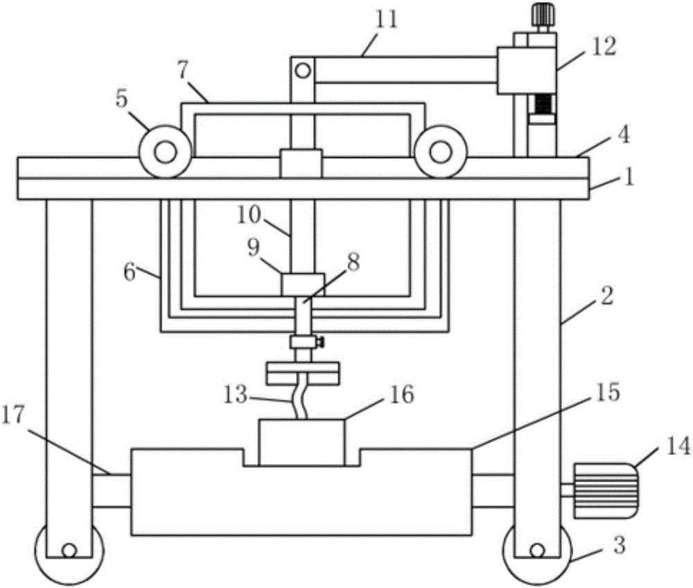
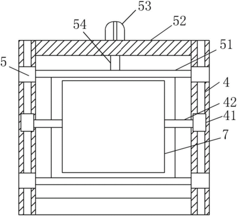
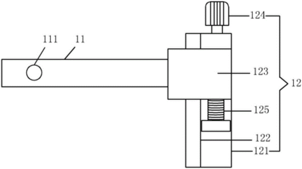
[0017] see Figure 1-5 , the present invention provides a technical solution: a pouring device for an engine main bearing cap, comprising a vehicle frame 1, legs 2 are provided at both ends of the bottom of the vehicle frame 1, rollers 3 are provided at the bottom of the legs 2, and the vehicle frame 1 is provided with a frame slide rail 4, the top of the frame slide rail 4 is provided with four sets of pulleys 5, the bottom of the frame 1 is provided with a p...


PUM


Abstract

The invention discloses a pouring device of an engine main bearing cover in the technical field of casting equipment. The pouring device comprises a frame. Landing legs are arranged at the two ends of the top of the frame. Wheels are arranged at the bottoms of the landing legs. Frame sliding rails are arranged on the top of the frame. A pouring base is arranged between four sets of pulleys. A pouring ladle is arranged in an inner cavity of the pouring base. A drainage hole is formed in the bottom of the pouring ladle. A blocking block is arranged on the top of the drainage hole, and the top of the blocking block is connected with a vertical rod. The top end of the vertical rod is connected with a cross rod. An elevating device is arranged on the right side of the top of one frame sliding rail. A pouring hose is arranged at the bottom of the pouring base. A trolley is arranged at the bottom of the pouring hose. A conveying motor is arranged on the right wall of the landing leg on the right side. A conveying belt is arranged on the outer wall of the rotation shaft. Safety production is facilitated, the production efficiency is greatly improved, and the labor intensity of workers is relieved. The pouring device is simple in structure, low in cost and convenient to use.

Description

technical field [0001] The invention relates to the technical field of casting equipment, in particular to a pouring device for an engine main bearing cap. Background technique [0002] At present, when the engine main bearing cap is vacuum poured, due to the large number of engine main bearing caps, one product requires one pouring hose, which increases the number of corresponding pouring hoses and valves, which causes many disadvantages. The cost of equipment manufacturing increases, and the castable remains in the pipeline, resulting in an increase in production cost, and it is troublesome to clean and clean the pouring hose. There are roughly the following types of casting and pouring of traditional engine main bearing caps: Two people are used to carry the ladle, and two sticks are used to fix the side of the ladle. People remove the slag in the molten steel near the ladle, which requires a lot of labor and high labor intensity. Pouring in the way of crane ladle, when...

Claims


Application Information

Patent Timeline
Patent Type & Authority Applications(China)
IPC IPC(8): B22D35/04B22D18/06
CPCB22D18/06B22D35/04
Inventor 林富全
Owner SHIFANG YONGSEN MACHINERY
Why Eureka
Try Eureka