Supercharge Your Innovation With Domain-Expert AI Agents!

Roller D-face machining jig of machining center

A machining center and roller technology, applied in the direction of chucks, etc., can solve problems such as difficulty in ensuring product processing quality, inaccurate positioning of fixtures, and single clamping of chucks, etc., to avoid product scrap, fast and accurate positioning, and ensure processing quality. Effect

Active Publication Date: 2017-05-31
中山市合丰五金制品有限公司
View PDF8 Cites 0 Cited by
  • Summary
  • Abstract
  • Description
  • Claims
  • Application Information

AI Technical Summary

Problems solved by technology

[0003] In the prior art, there are still many deficiencies in the jigs for producing and processing the D surface of the roller. The chucks are generally fixed and single, and it is difficult to replace them according to the model being processed. The scope of application is narrow, and the existing The positioning of the production and processing roller D surface jig is not accurate, and the positioning process is slow, which not only affects the production efficiency, but also makes it difficult to guarantee the processing quality of the product. Therefore, the existing production and processing roller D surface jig can no longer meet people's needs. A kind of jig for processing roller D surface of a machining center to solve the above-mentioned problems

Method used


Image

  • Roller D-face machining jig of machining center
  • Roller D-face machining jig of machining center
  • Roller D-face machining jig of machining center

Examples


specific Embodiment approach

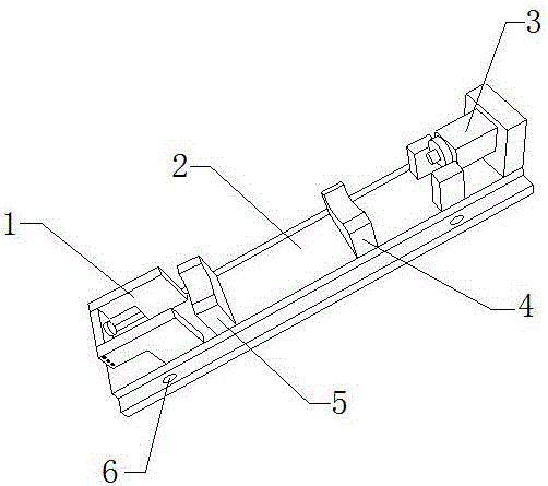
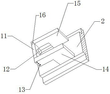
[0024] Specific embodiments: first, the user checks whether the present invention is damaged, and if there is no damage, it can continue to be used. During use, the user uses the fixing hole 13 to install the present invention on the required position, and the user selects the required chuck 12 Finally, the positioning bar 16 is installed in the positioning groove, and the chuck seat 11 is pressed down. When the chuck seat 11 is pressed to the desired position, the user uses the hexagon socket head screw to fix the chuck seat 11 to This realizes fast fixed installation of the chuck 12 and facilitates later replacement.

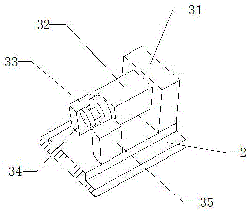
[0025] The user places the roller to be processed in the arc groove on the support block one 4 and the support block two 5, and after fixing one end of the roller to be processed on the chuck 12, the user moves the pneumatic cylinder 32, the pneumatic cylinder The elongation of 32 drives the rubber disc 34 to move, and then the rubber disc 34 is fixed on the o...


PUM


Abstract

The invention provides a roller D-face machining jig of a machining center. The roller D-face machining jig of the machining center comprises a chuck seat, a chuck, fixing holes, a supporting frame I, a supporting frame II, a positioning strip, a fixing plate, a pneumatic cylinder, a limiting plate I, a rubber disc and a limiting plate II, wherein the positioning strip is installed in the middle of the rear end surface of the chuck seat; the front end surface of the supporting frame I and the rear end surface of the supporting frame II are both provided with the fixing holes; and the chuck is assembled in the middle of the right end surface of the chuck seat. The design realizes rapid installation and replacement of the roller D-face machining jig of the machining center, and the application range of the roller D-face machining jig of the machining center is greatly widened. The fixing plate is welded to the edge of the right side of the upper end surface of a base. The limiting plate I and the limiting plate II are symmetrically installed on the upper end surface of the base. The pneumatic cylinder is installed in the middle of the left end surface of the fixing plate. The rubber disc is assembled on the pneumatic cylinder. By means of the design, accuracy and stability of positioning of the roller D-face machining jig of the machining center are improved, and the roller D-face machining jig of the machining center is rapid and accurate in positioning, wide in application range, good in stability and high in reliability.

Description

technical field [0001] The invention relates to a jig for machining a roller D surface of a machining center, which belongs to the field of fixture equipment. Background technique [0002] Machining center, referred to as CNC, is a high-efficiency automatic machine tool composed of mechanical equipment and numerical control system used for processing complex-shaped workpieces. Machining center is also called computer gong. The machining center is equipped with a tool magazine and has the function of automatic tool change. It is a CNC machine tool that performs multi-process processing after the workpiece is clamped once. Fixtures are a large class of tools for woodworking, ironwork, fitter, machinery, electric control and other handicrafts, mainly as a tool to assist in controlling position or movement (or both). [0003] In the prior art, there are still many deficiencies in the jigs for producing and processing the D surface of the roller. The chucks are generally fixed ...

Claims


Application Information

Patent Timeline
IPC IPC(8): B23B31/16
CPCB23B31/16025
Inventor 叶国宾宋海平宋磊
Owner 中山市合丰五金制品有限公司
Features
  • R&D
  • Intellectual Property
  • Life Sciences
  • Materials
  • Tech Scout
  • Unparalleled Data Quality
  • Higher Quality Content
  • 60% Fewer Hallucinations
Learn More