
Multihole machining tool of end face of air cylinder sleeve

A hole machining and cylinder liner technology, applied in the field of locomotive cylinder liner end face porous machining tooling and machining tooling, can solve the problems of complicated positioning operation, high consumption cost, increase the height of the object to be processed, etc., to simplify the positioning operation and reduce the positioning Difficulty, the effect of ensuring accuracy

Inactive Publication Date: 2017-05-31
襄阳襄车铁达缸套铸业有限公司
View PDF0 Cites 1 Cited by
  • Summary
  • Abstract
  • Description
  • Claims
  • Application Information

AI Technical Summary

Problems solved by technology

The porous processing tool of the prior art has the following disadvantages: one is that the general drilling tool has many parts, the operation is complicated, and the drilling efficiency is low; Clamping the fixture and the workpiece increases the height of the object to be processed and increases the difficulty of operation; the third is that the positioning device of the drilling tool uses positioning keys, positioning nuts, etc., which need to be drilled on the cylinder liner to match the positioning and damage The integrity of the object to be processed is guaranteed; the fourth is that most of the drilling hole sleeves on the drilling tooling are welded on the tooling in a non-detachable manner. With the damage of the drilling sleeve, the accuracy of drilling decreases, and finally the tooling can only be replaced. , the consumption cost is high, and the flange of a few detachable drilling sleeves is circular. When the drill bit is not positioned correctly, it is necessary to move the drill bit up or move down to position the object to be processed. The positioning operation is complicated and the drilling efficiency is low.
Fifth, the drill sleeve is generally installed directly in the mold hole, and there is a gap between the drill sleeve and the mold hole. When the drill bit is not positioned correctly and pressure is applied to the drill sleeve, the drill sleeve will shift, resulting in low drilling accuracy.

Method used


Image

  • Multihole machining tool of end face of air cylinder sleeve
  • Multihole machining tool of end face of air cylinder sleeve

Examples


Embodiment Construction

[0016] The present invention will be further described below in conjunction with specific embodiments.

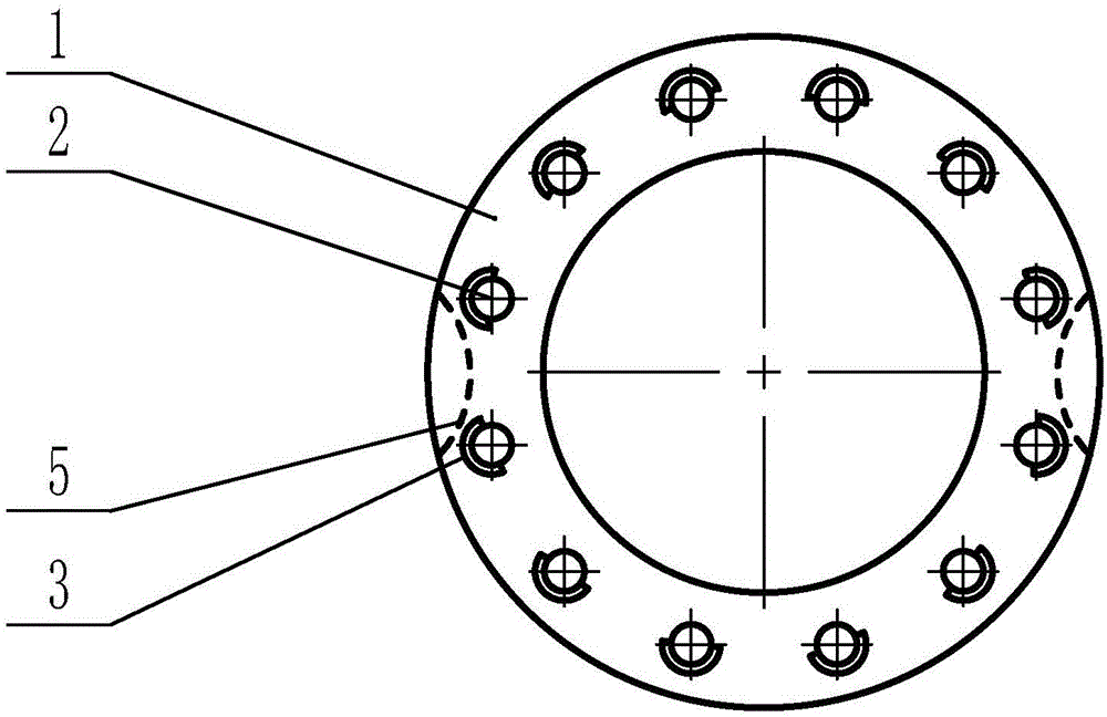
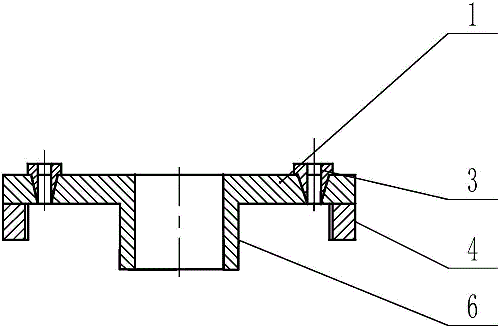
[0017] see figure 1 , figure 2 , a cylinder liner end face porous processing tooling of the present invention, comprising a drill template 1, the drill template 1 is circular cylindrical, and more than one die hole 2 is evenly arranged on the drill template 1 along the same circumference, and the die hole 2 is sleeved There is a drill sleeve 3, and also includes a positioning block 4, which is fixedly connected with the drilling template 1, and the positioning block 4 can be fixedly connected with the drilling template 1 by welding, or can be movably connected with the drilling template 1 by means of bolts, etc. The shape of the block 4 matches that of the arc-shaped notch 5 on the end face of the cylinder liner. When the cylinder liner is assembled with the cylinder liner, the assembly bolts are placed in the arc-shaped notch 5 . There is no need to clamp the parts wit...


PUM


Abstract

The invention provides a multihole machining tool of an end face of an air cylinder sleeve. The machining tool comprises a drill plate (1), wherein the drill plate (1) is an circular column; one or more die holes (2) are uniformly formed in the drill plate (1) along the same circumference; drill bushings (3) are connected into the die holes (2) in a sleeving manner; the machining tool further comprises locating blocks (4); the locating blocks (4) are fixedly connected with the drill plate (1); the shapes of the locating blocks (4) are matched with those of circular arc notches (5) of the air cylinder sleeve; the drill bushings (3) are internally provided with cylindrical through holes; external walls of the drill bushings (3) are conical; hole walls of the die holes (2) are conical; and the drill bushings (3) are matched and connected with the die holes (2). The machining tool is convenient and accurate in location, simple to operate, low in machining cost, good in drilling machining effect and high in machining efficiency and is particularly applicable to multihole machining of the end face of the air cylinder sleeve of a locomotive.

Description

technical field [0001] The invention relates to a processing tool, in particular to a porous processing tool for the end face of a locomotive cylinder liner, and belongs to the technical field of mechanical processing. Background technique [0002] The cylinder liner end face porous processing tool is a tooling fixture for assisting cylinder liner end face drilling. Its function is to ensure the accuracy of the drilling position of the cylinder liner end face and improve the efficiency of drilling processing. The porous processing tool of the prior art has the following disadvantages: one is that the general drilling tool has many parts, the operation is complicated, and the drilling efficiency is low; Clamping the fixture and the workpiece increases the height of the object to be processed and increases the difficulty of operation; the third is that the positioning device of the drilling tool uses positioning keys, positioning nuts, etc., which need to be drilled on the cyl...

Claims


Application Information

Patent Timeline
IPC IPC(8): B23B47/28
CPCB23B47/28
Inventor 余光军林小平卢安平
Owner 襄阳襄车铁达缸套铸业有限公司
Learn More