

Guide ail protecting cover device of end facing machine, guide rail protecting method and end facing machine
A technology of flat head machine and protective cover, which is applied in the field of flat head machine, which can solve the problems of reducing the processing efficiency and quality of flat head machining, and achieve the effects of improving processing efficiency and processing quality, increasing versatility, and convenient and quick adjustment
- Summary
- Abstract
- Description
- Claims
- Application Information
AI Technical Summary
Problems solved by technology
Method used
Image

Examples
Embodiment 1
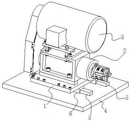
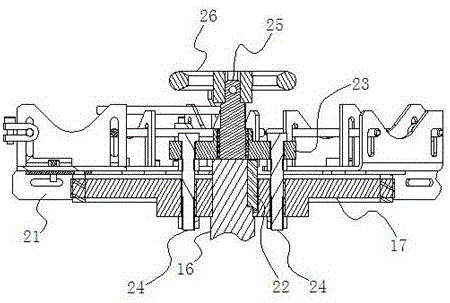
[0039] Embodiment 1: as Figure 2 to Figure 5 As shown, a guide rail protective cover device of a flat head machine, which includes a slider connecting plate 7 and a guide rail guard plate 8, the longitudinal section of the slider connecting plate 7 is U-shaped, and on the outside of one side of the slider connecting plate 7 The horizontal connecting plate 9 and the slider connecting plate 7 are integrated, and the end of the other side of the slider connecting plate 7 is connected to the bottom of the base plate 1 of the cutter head device, and the horizontal connecting plate There is a gap-10 between the top of 9 and the base plate 1, and the slide block 6 of the knife head device is connected to the bottom of the horizontal connecting plate 9 by screws, thereby connecting the slide block 6 with the base plate 1;
[0040] The longitudinal section of the guide rail guard 8 is an inverted U shape, and one side of the guide rail guard 8 is connected to the working platform 4 of...
Embodiment 2
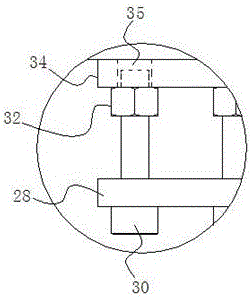
[0050] Embodiment 2: as Figure 12 with Figure 13 As shown, compared with Embodiment 1, the difference is that a positioning lug 36 is provided at the angle between one side of the slider connecting plate 7 and the horizontal connecting plate 9, and the positioning lug 36 and the slider are connected. The plate 7 and the horizontal connecting plate 9 are integrated, the top of the slider 6 is in contact with the bottom of the horizontal connecting plate 9, one side of the slider 6 is in contact with the side of the positioning projection 36, and the sliding block is connected by connecting screws. The block is connected on the bottom of the horizontal connecting plate, thus connecting the slider 6 with the bottom plate 1 . In this embodiment, when the slider is installed, the slider is positioned by using the additional positioning bump in contact with the slider. It is only necessary to perform precision machining on the contact surface of the positioning bump and the slide...
Embodiment 3
[0051] Embodiment 3: as Figure 14 with Figure 15 As shown, compared with Embodiment 1, the difference is that there is a gap 2 37 between the bottom edge of the slider connecting plate 7 and the working platform 4, and the guide rail protective cover device of the flat head machine also includes side guards 38 One end of the side guard plate 38 is connected to the base plate 1 of the cutter head device, and there is a gap three 39 between the other end of the side guard plate 38 and the working platform 4 and the gap three 39 is smaller than the gap two 37 . In order to prevent falling debris from entering the guide rail from the bottom edge of the slider connecting plate after rebounding on the working platform, side guards are added in this embodiment to further strengthen the tightness of the protection space.
[0052] To sum up, the guide rail protective cover device of the present invention hides the guide rail in the protective space inside the guide rail guard plate ...
PUM
 Abstract
Description
Claims
Application Information