Reciprocating type polisher

A grinding machine and reciprocating technology, which is applied in the manufacturing field, can solve the problems of large occupied area, low efficiency, and low grinding efficiency, and achieve the effects of occupying less floor space, saving workshop area, and facilitating manufacturing

Inactive Publication Date: 2017-05-31
重庆王滔机械制造有限公司
View PDF6 Cites 12 Cited by
  • Summary
  • Abstract
  • Description
  • Claims
  • Application Information

AI Technical Summary

Problems solved by technology

[0002] Steel is an indispensable building material in various fields of society, but steel is easy to rust and corrode in the atmospheric environment. After rusting, the oxidized part of the surface of the steel must be removed before anti-corrosion treatment; the current grinding Usually, hand-held grinders are used for grinding, which is very inefficient and because the quality of manual grinding is not high, it is easy to cause some parts to be too deep, which affects the strength of the steel after grinding; the conventional disc grinder occupies a large area and is inconvenient to operate
[0003] After the steel is cut, burrs will appear at the cutting place; the efficiency of manual grinding is low, and the grinding quality cannot be controlled

Method used


Image

  • Reciprocating type polisher
  • Reciprocating type polisher
  • Reciprocating type polisher

Examples


Embodiment 1

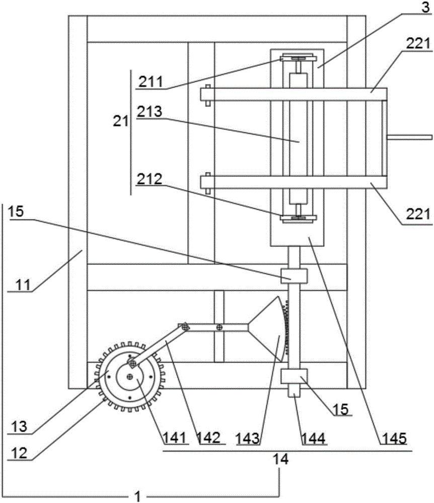
[0026] as follows figure 1 As shown, the reciprocating grinder includes a reciprocating mechanism 1 and a clamping mechanism 2; the reciprocating mechanism 1 is installed on the ground; the clamping mechanism 2 is installed on the reciprocating mechanism 1; the reciprocating mechanism 1 includes a frame 11, Motor 12, reduction mechanism 13, connecting rod 142 gear mechanism 14; Described motor, reduction mechanism 13, connecting rod 142 gear mechanism 14 are installed on the frame 11; The power output end of described motor 12 and the power input of reduction mechanism 13 The power output end of the reduction mechanism 13 is fixedly connected with the power input end of the connecting rod 142 gear mechanism 14; the connecting rod 142 gear mechanism 14 includes a cam 141, a connecting rod 142, a sector gear rod 143, a rack 144; the cam 141 is splined to the power output end of the reduction mechanism 13; the protrusion of the cam 141 is hinged to one end of the connecting rod 1...

Embodiment 2

[0036] as follows Figure 5As shown, the reciprocating grinder includes a reciprocating mechanism 1 and a clamping mechanism 2; the reciprocating mechanism 1 is installed on the ground; the clamping mechanism 2 is installed on the reciprocating mechanism 1; the reciprocating mechanism 1 includes a frame 11, Motor 12, reduction mechanism 13, connecting rod 142 gear mechanism 14; Described motor, reduction mechanism 13, connecting rod 142 gear mechanism 14 are installed on the frame 11; The power output end of described motor 12 and the power input of reduction mechanism 13 The power output end of the reduction mechanism 13 is fixedly connected with the power input end of the connecting rod 142 gear mechanism 14; the connecting rod 142 gear mechanism 14 includes a cam 141, a connecting rod 142, a sector gear rod 143, a rack 144; the cam 141 is splined to the power output end of the reduction mechanism 13; the protrusion of the cam 141 is hinged to one end of the connecting rod 1...


PUM


Abstract

The invention discloses a reciprocating type polisher which comprises a reciprocating mechanism and a clamping mechanism. The reciprocating mechanism is mounted on the ground, and the clamping mechanism is mounted on the reciprocating mechanism which comprises a rack, a motor, a reducing mechanism and a connecting rod gear mechanism. The motor, the reducing mechanism and the connecting rod gear mechanism are mounted on the rack. The power output end of the motor is fixedly connected with the power input end of the reducing mechanism, and the power output end of the reducing mechanism is fixedly connected with the power input end of the connecting rod gear mechanism. According to the reciprocating type polisher, reciprocating type polishing is achieved through the low-price torque motor, the outer surface and the inner surface of an object can be polished through the reciprocating type polisher, the polishing thickness can be controlled, and the polishing efficiency is high; and the reciprocating type polisher is simple in structure, low in construction cost, convenient to maintain, easy to operate, high in precision and small in occupied area, and the operating cost of an enterprise is saved.

Description

technical field [0001] The invention relates to the field of manufacturing, in particular to a reciprocating grinder. Background technique [0002] Steel is an indispensable building material in various fields of society, but steel is easy to rust and corrode in the atmospheric environment. After rusting, the oxidized part of the surface of the steel must be removed before anti-corrosion treatment; the current grinding Hand-held grinding machines are usually used for grinding, which is very inefficient and because the quality of manual grinding is not high, it is easy to cause some parts to be too deep, which affects the strength of the steel after grinding; conventional disc grinding machines occupy a large area and are inconvenient to operate. [0003] After the steel is cut, burrs will appear at the cutting place; the efficiency of manual grinding is low, and the grinding quality cannot be controlled. Contents of the invention [0004] The object of the present inventi...

Claims


Application Information

Patent Timeline
Patent Type & Authority Applications(China)
IPC IPC(8): B24B27/033B24B9/04B24B41/06B24B47/16
CPCB24B27/033B24B9/04B24B41/06B24B47/16
Inventor 王嘉富
Owner 重庆王滔机械制造有限公司
Why Eureka
Try Eureka