Hall type pedal location sensor and brake pedal device

A technology of pedal position and brake pedal, which is applied in the field of vehicles, can solve problems such as abnormal contact noise and unreliable conduction, and achieve the effect of fewer internal parts, stable and reliable quality, and reduced mold development

Inactive Publication Date: 2017-05-31
CHERY AUTOMOBILE CO LTD
View PDF7 Cites 5 Cited by
  • Summary
  • Abstract
  • Description
  • Claims
  • Application Information

AI Technical Summary

Problems solved by technology

[0004] In view of this, the present invention provides a Hall-type pedal position sensor and a brake pedal device to solv

Method used


Image

  • Hall type pedal location sensor and brake pedal device
  • Hall type pedal location sensor and brake pedal device
  • Hall type pedal location sensor and brake pedal device

Examples


Example Embodiment

[0032] In order to make the technical solutions and advantages of the present invention clearer, the following further describes the embodiments of the present invention in detail with reference to the accompanying drawings.

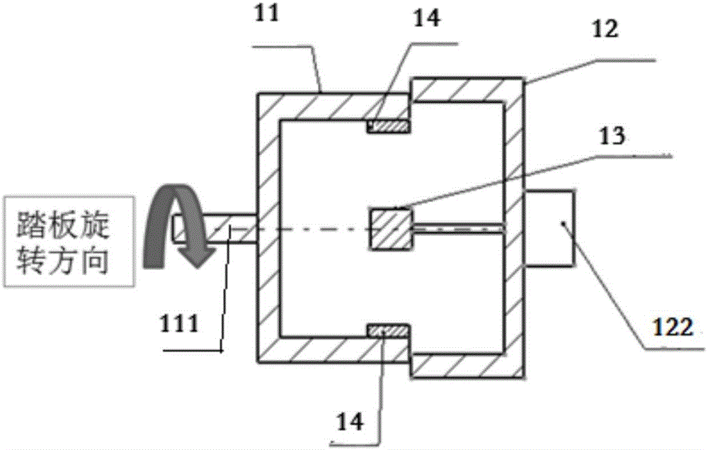
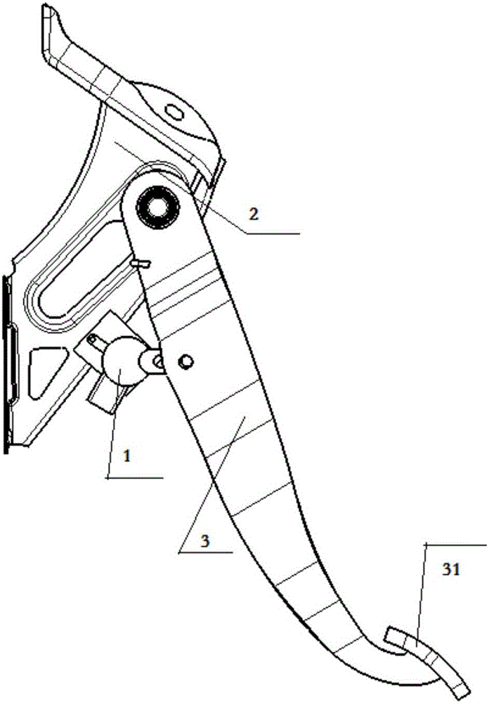
[0033] The first embodiment of the present invention provides a Hall-type pedal position sensor, such as figure 1 , 2 As shown, it includes a first housing 11, a second housing 12, a Hall device 13 and a magnet 14.

[0034] The first housing 11 and the second housing 12 are rotatably assembled together to form an inner cavity. The first shell 11 and the second shell 12 are hollow parts to form an inner cavity, and their mating parts generally have a circular ring shape, so that they can be relatively rotated, and can be prevented from being easily separated by fitting with a slot. Can be like figure 1 Then the radius of the first shell 11 is smaller than the second shell 12, or as figure 2 That way, the radius of the first shell 11 is larger than that of the...


PUM


Abstract

The invention provides a hall type pedal location sensor. The location sensor comprises a first shell, a second shell, a hall device and a magnet, wherein the first shell and the second shell can be relatively rotationally assembled together to form an inner cavity; a rotational connection piece is fixedly arranged on the first shell, the first shell is fit for being driven to rotate through a rotational connection piece; a fastening connection piece is fixedly arranged on the second shell, the second shell is fit for being fastened through the fastening connection piece; the hall device is arranged on an inner cavity, and is fastened on either one of the first shell and the second shell; the magnet is arranged on the inner cavity, and is fastened on the other one of the first shell and the second shell; when the first shell and the second shell rotate relative to each other, varying voltage signals are produced by the hall device because of the location changes relative to the magnet. According to the hall type pedal location sensor and the brake pedal device, the problems of touch abnormal noises of the traditional mechanical brake switches and unreliable breakovers caused by abrasions are solved.

Description

technical field [0001] The invention relates to the technical field of vehicles, in particular to a Hall-type pedal position sensor and a brake pedal device. Background technique [0002] The role of the brake switch on modern cars With the continuous improvement of people's living standards, the requirements for cars are getting higher and higher. Modern cars are developing towards safety, comfort, and environmental protection. The brake light switch of modern cars is not only to control the brake light, more and more systems need the brake switch signal, such as electronically controlled fuel system, automatic transmission, ABS brake anti-lock braking system, automatic cruise system, ESP system, PEPS Systems, etc., have higher and higher requirements for switches. [0003] At present, the brake switch on most cars is located above the brake pedal and fixed on the brake pedal bracket. When the brake pedal is inactive, press the switch, and the internal contacts of the swit...

Claims


Application Information

Patent Timeline
IPC IPC(8): B60T7/06B60T17/22G01B7/00
CPCB60T7/06B60T17/22G01B7/003
Inventor 金跃川刘金平
Owner CHERY AUTOMOBILE CO LTD
Why Eureka
Try Eureka