Water removing device for oil storage tank

An oil storage tank, oil tank technology, applied in the direction of tanker, packaging, transportation and packaging, can solve the problems of polluting the environment, inability to discharge water, waste of oil products, etc.

Active Publication Date: 2017-05-31
LOGISTICAL ENGINEERING UNIVERSITY OF PLA +2
View PDF8 Cites 3 Cited by
  • Summary
  • Abstract
  • Description
  • Claims
  • Application Information

AI Technical Summary

Problems solved by technology

When there is only a small amount of water in the oil storage tank, if the water cutter is used, on the one hand, the water cannot be completely discharged, and on the other hand, the oil content of the drained water is high, which not only causes waste of oil, but also pollutes the environment, and there is a huge risk Security risks
At the same time, some microorganisms will produce surfactants after being oleophilic, which will emulsify the oil, and the grade of the oil will be greatly reduced after emulsification.
Therefore, in addition to the water cutter to remove water in the oil storage tank, or export the oil through the oil-water separator for separation, the power source in this process is electricity, which has potential unsafe factors for the oil.

Method used


Image

  • Water removing device for oil storage tank
  • Water removing device for oil storage tank
  • Water removing device for oil storage tank

Examples


Embodiment Construction

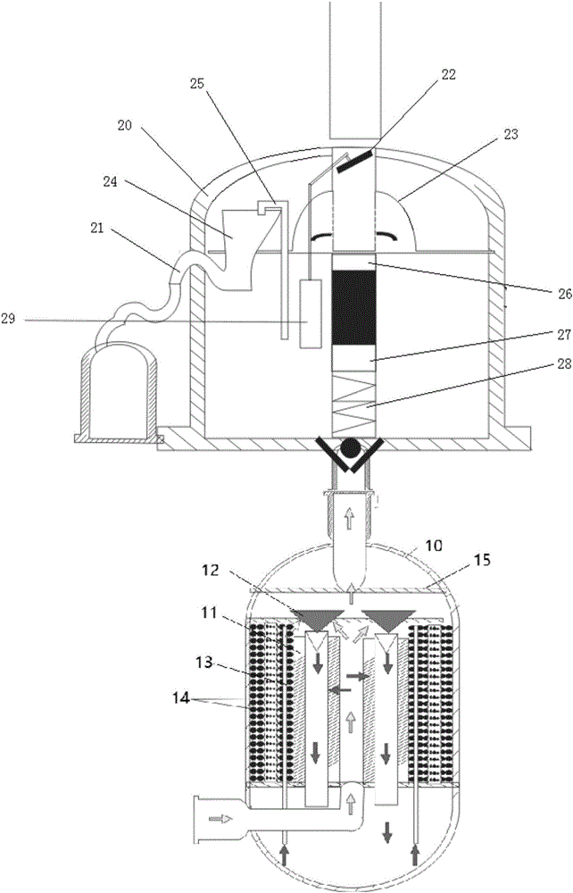
[0039] Such as Figure 1-3 As shown, an embodiment of the present invention provides a water removal device for an oil storage tank, including:

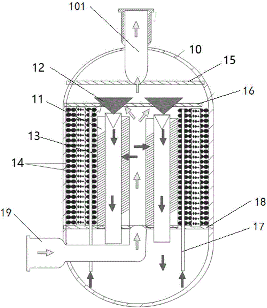
[0040] The oil tank filter separator 10 is provided with a crude oil inlet pipe 19 at the bottom of the tank body, and is used for oil-water separation of the water-containing oil that enters the tank body of the oil tank filter separator 10 through the crude oil inlet pipe 19;

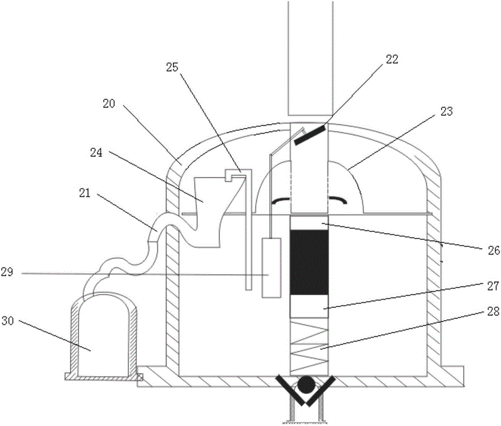
[0041] The float device 20 , the inlet of the float device 20 is connected to the liquid outlet at the top of the filter separator 10 , and the oil liquid entering the float device 20 is discharged through the siphon device 30 .

[0042] Preferably, the tank body of the filter separator 10 is provided with an upper partition 16 and a lower partition 18, and a separation space is formed between the upper partition 16, the lower partition 18 and the inner wall of the tank, and the lower partition A collection space is formed between the bottom of the plate 18...


PUM


Abstract

The invention provides a water removing device for an oil storage tank. The water removing device comprises an oil tank filtering separator and a floating ball device, a crude oil inlet pipe is arranged on the bottom of a tank body, and the oil tank filtering separator is used for carrying out oil-water separation on water-contained oil entering the tank body of the oil tank filtering separator through the crude oil inlet pipe; and an inlet of the floating ball device is connected with a liquid outlet in the top of the filtering separator, and oil entering the floating ball device is drained through a siphon device. By means of the oil-water separation process in inner circulation of the water removing device, water is separated and concentrated in the lower tank body of the device after hydrone enters the oil tank from the outside and before the hydrone forms large-scale water mass.

Description

technical field [0001] The invention relates to the technical field of oil storage tanks, in particular to a water removal device for oil storage tanks. Background technique [0002] Microorganisms grow and multiply to form slime-like biofilms containing inorganic and organic debris. Biofilms can form on tank tops, in fuel, at tank bottoms and water interfaces, and on all system surfaces. Water activity is greatest at the interface such as oil and water, so the interface is most likely to form microbial groups or biofilms. [0003] Biofilm populations produced by microbial contamination are directly involved in corrosion, leading to microporous leaks in tanks and pipelines. Sulfate-reducing bacteria and other anaerobic bacteria consume hydrogen ions, accelerating corrosion reactions. Hydrogen sulfide produced by sulfate-reducing bacteria acidifies the fuel and causes corrosion in the system; organic acids such as formic acid, acetic acid, and lactic acid with low molecula...

Claims


Application Information

Patent Timeline
Patent Type & Authority Applications(China)
IPC IPC(8): B65D88/74B01D17/02
CPCB01D17/0202B65D88/74
Inventor 朱鹏熊云江景坡范建忠范林君许世海刘晓苏鹏李鹏秦敏刘萍章礼平黄海龙敬秋
Owner LOGISTICAL ENGINEERING UNIVERSITY OF PLA
Why Eureka
Try Eureka