
Oil-gas recovering system of storage tank and control method thereof

A technology of oil and gas recovery system and storage tank, which is applied in the field of oil and gas recovery of storage tanks, and can solve problems such as low operating efficiency, large design scale, and unreasonable processing capacity of the oil and gas recovery system

Active Publication Date: 2017-05-31
谢玉勋
View PDF5 Cites 6 Cited by
  • Summary
  • Abstract
  • Description
  • Claims
  • Application Information

AI Technical Summary

Problems solved by technology

[0003] In the existing technology, based on the operating characteristics of liquid oil production and storage enterprises, the processing capacity of the oil and gas recovery system is designed according to the maximum peak value, resulting in a large design scale of the device, low operating efficiency, high production costs, and low relative returns
At the same time, due to the unreasonable design of the processing capacity of the oil and gas recovery system, the operation of the oil and gas recovery system is in a violent alternating state, which aggravates the fatigue of the equipment and high safety risks

Method used


Image

  • Oil-gas recovering system of storage tank and control method thereof
  • Oil-gas recovering system of storage tank and control method thereof
  • Oil-gas recovering system of storage tank and control method thereof

Examples


Embodiment 1

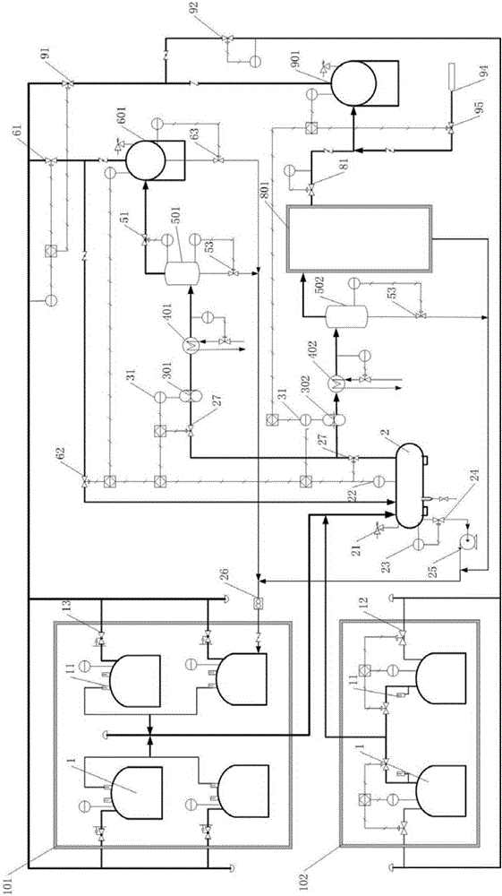
[0085] figure 1 A schematic diagram of the process flow of the storage tank oil gas recovery system provided by the embodiment of the present invention, as shown in figure 1 As shown, in this embodiment, the series oil and gas collection method is adopted.

[0086] This embodiment provides a storage tank oil and gas recovery system, including a storage tank 1, a liquid separation tank 2, a first compressor 301, a second compressor 302, a first separation tank 501, a second separation tank 502, a balance tank 601, The oil and gas recovery device 801 and the buffer tank 901, the storage tank 1 is connected with the nitrogen blanketing system; the oil and gas outlet of the storage tank 1 is connected with the inlet of the liquid separation tank 2, the first compressor 301, the first separation tank 501 and the balance tank 601 in sequence , the outlet of the balance tank 601 is respectively connected with the air inlet of the liquid separation tank 2 and the suction port of the ...

Embodiment 2

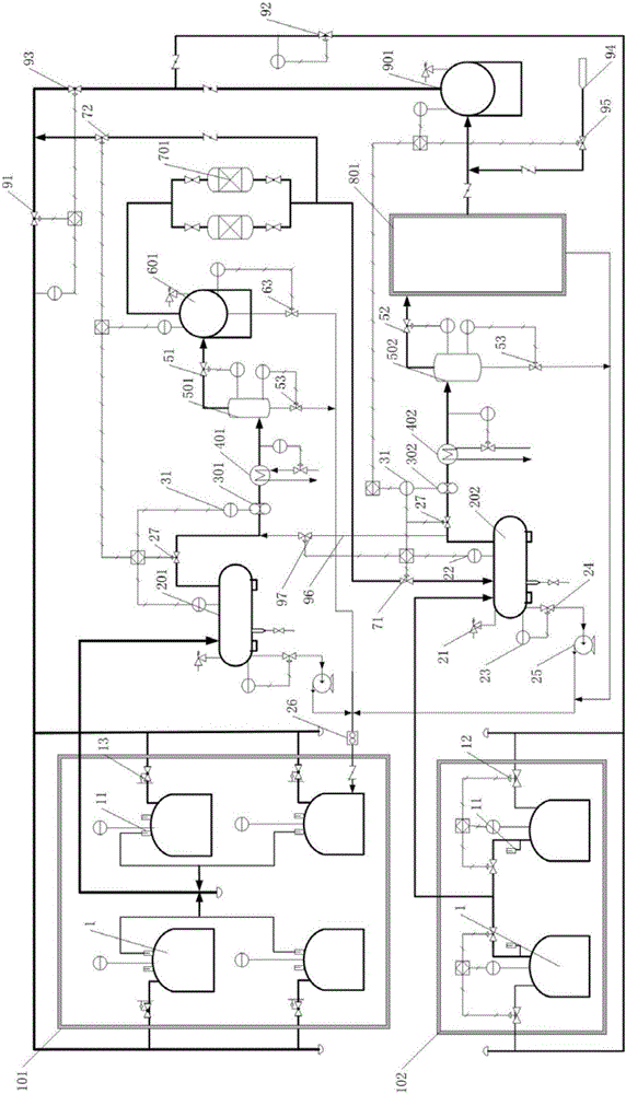
[0096] figure 2 Another schematic diagram of the process flow of the storage tank oil and gas recovery system provided by the embodiment of the present invention, such as figure 2 As shown, in this embodiment, the series oil and gas collection method is adopted.

[0097] This embodiment provides a storage tank oil and gas recovery system, including a storage tank 1, a liquid separation tank 2, a first compressor 301, a second compressor 302, a first separation tank 501, a second separation tank 502, a balance tank 601, The oil and gas recovery device 801 and the buffer tank 901, the storage tank 1 is connected with the nitrogen blanketing system; the oil and gas outlet of the storage tank 1 is connected with the inlet of the liquid separation tank 2, the first compressor 301, the first separation tank 501 and the balance tank 601 in sequence , the outlet of the balance tank 601 is respectively connected with the air inlet of the liquid separation tank 2 and the suction port...

Embodiment 3

[0106] This embodiment provides a control method for the storage tank oil and gas recovery system as described in Embodiment 1 and Embodiment 2, which specifically includes:

[0107] (1) System pressure control:

[0108] The pressure of the oil and gas balance system is controlled by the pressure of the first separation tank 501, and the pressure of the oil and gas recovery system is controlled by the pressure of the second separation tank 502 or the outlet pressure of the oil and gas recovery device 801, specifically:

[0109] Set the pressure of the first separation tank 501 according to the large breathing volume of the storage tank 1, the total amount of small breathing gas and the floor area, and control the oil-gas balance system through the pressure control valve 51 on the gas phase outlet connection pipeline of the first separation tank 501 pressure;

[0110] Set the pressure of the second separation tank 502 according to the type of the oil vapor recovery device 801 ...


PUM


Abstract

The invention relates to the technical field of the oil-gas recovery technology of the storage tank and in particular to an oil-gas recovering system of a storage tank and a control method thereof. The provided oil-gas recovering system of the storage tank comprises the storage tank, a fluid distributing tank, a first compressor, a second compressor, a first separating tank, a second separating tank, a balance tank, an oil-gas recovering device and a buffering tank. The storage tank is successively connected with the fluid distributing tank, the first compressor, the first separating tank and the balance tank. The balance tank is respectively connected with the fluid distributing tank and the storage tank to form an oil-gas balance system. The storage tank is successively connected with the fluid distributing tank, the second compressor, the second separating tank, the oil-gas recovering device, the buffering tank and the storage tank to form the oil-gas recovering system. The oil-gas recovering system of the storage tank is capable of, through the setting of the balance tank, reducing the design load of the oil-gas recovering device, maintaining the stable running of the oil-gas recovering device, avoiding the frequent and great alternating running of the device, reducing the alternating fatigue of the device, and reducing the safety risk. The compared with the current oil-gas recovering device, the design load is reduced by 50%-80%.

Description

technical field [0001] The invention relates to the technical field of storage tank oil gas recovery technology, in particular to a storage tank oil gas recovery system and a control method thereof. Background technique [0002] For the production and storage enterprises of liquid oil products, the raw materials and products in the oil product storage tanks organize production operations through various transportation methods. It can be transported by ships, vehicles or pipelines, and regardless of ships, vehicles or pipelines, the common characteristic is intermittent operation, which makes the large breathing of oil storage tanks in an irregular zigzag shape, and is affected by the temperature difference between day and night. The impact makes the oil storage tank's small breath in a wave state. [0003] In the existing technology, based on the operating characteristics of liquid oil production and storage enterprises, the processing capacity of the oil and gas recovery s...

Claims


Application Information

Patent Timeline
IPC IPC(8): B65D90/30
CPCB65D90/30
Inventor 谢玉勋
Owner 谢玉勋
Learn More