
Chain-delivered winding shaft for winder

A technology of rewinding shaft and rewinding machine, applied in the direction of winding strip, thin material handling, transportation and packaging, etc., can solve the problems of impact, noise, vibration and so on

Inactive Publication Date: 2017-05-31
大连橡胶塑料机械有限公司
View PDF8 Cites 2 Cited by
  • Summary
  • Abstract
  • Description
  • Claims
  • Application Information

AI Technical Summary

Problems solved by technology

[0002] Plastic blown film equipment equipped with a winder, due to the working process steps of the winder, when the winder starts to roll a new roll of plastic film, it needs to transport the winding shaft to the initial winding position of the winding shaft, due to the storage position of the winding shaft There is a certain drop to the initial coiling position of the reeling shaft. The reeling shaft has a certain weight, and there is a certain impact when it falls to the initial coiling position. The change of the position of the actuator, especially the inconsistency of the rewinding shaft due to the inconsistency of each impact position, causes the interruption of the continuous steps of the rewinder, resulting in the interruption of the plastic film products from the upstream at the rewinder, resulting in waste of products

Method used


Image

  • Chain-delivered winding shaft for winder
  • Chain-delivered winding shaft for winder
  • Chain-delivered winding shaft for winder

Examples


Embodiment Construction

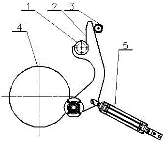
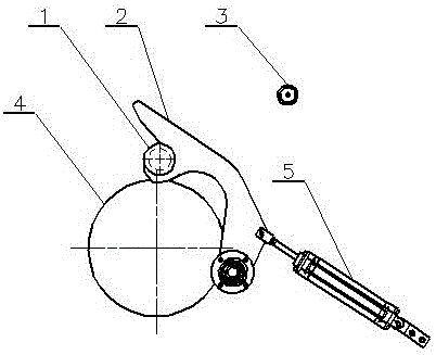
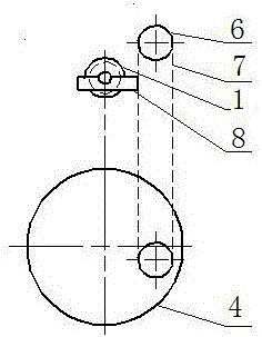
[0012] Such as Figure 1 to Figure 4 As shown, the winding machine chain delivers the winding shaft, including the winding shaft 1, the crank arm 2, the limit block 3, the friction roller 4, the cylinder 5, the sprocket 6, the chain 7 and the support plate 8, and the winding shaft 1 is arranged on the crank arm 2, the curved arm 2 is connected with the cylinder 5, the friction roller 4 is connected with the curved arm 2, the sprocket 6 is connected with the chain 7, and the support plate 8 is fixed on the chain 7. The present invention uses the chain to move up and down in a straight line to deliver, and the take-up shaft falls To the initial winding position, the chain is driven by a motor to move, and the support plate supports the winding shaft to move up and down with the chain. The designed moving speed of the winding shaft is low and will not cause impact, which overcomes the traditional winding shaft rotation and delivery due to the weight. The impact of the reel on the...


PUM


Abstract

The invention discloses a chain-delivered winding shaft for a winder. The chain-delivered winding shaft comprises a winding shaft body, a crank arm, a friction roller, a cylinder, a chain wheel, a chain and a supporting plate, wherein the winding shaft body is arranged on the crank arm; the crank arm is connected with the cylinder; the friction roller is connected with the crank arm; the chain wheel is connected with the chain; and the supporting plate is fixed on the chain. According to the chain-delivered winding shaft, the chain is adopted for up-and-down linear movement delivery to enable the winding shaft body to fall to an initial wind-up position, a motor is adopted to drive the chain to move, the supporting plate for supporting the winding shaft body is fixed on the chain through bolts and supports the winding shaft body to move up and down along with the chain, and the movement speed depends on the speed ratio of a motor reducer. The designed winding shaft is low in movement speed, and accordingly, cannot generate impact, so that the problem that during rotary delivery of a traditional winding shaft, the winding shaft falls down in an accelerated manner due to the weight action, and consequently impacts equipment is solved, noise of the equipment is lowered, steady falling of the winding shaft is realized, and the working stability of the winder is improved.

Description

technical field [0001] The invention relates to a winding machine chain delivery winding shaft. Background technique [0002] Plastic blown film equipment equipped with a winder, due to the work process steps of the winder, when the winder starts to roll a new roll of plastic film, it needs to transport the winding shaft to the initial winding position of the winding shaft, due to the storage position of the winding shaft There is a certain drop to the initial coiling position of the winding shaft, and the coiling shaft has a certain weight, and there is a certain impact when it falls to the initial coiling position. The change of the position of the actuator, especially the inconsistency of the position of the rewinding shaft due to the inconsistency of each impact position causes the interruption of the continuous steps of the rewinder, which causes the interruption of the upstream plastic film products at the rewinder, resulting in waste of products. Contents of the inv...

Claims


Application Information

Patent Timeline
IPC IPC(8): B65H19/30
CPCB65H19/30B65H2301/417B65H2701/1133B65H2701/1752
Inventor 刘守胜吕剑锐
Owner 大连橡胶塑料机械有限公司
Learn More