
A cloth transfer mechanism

A transfer mechanism and fabric technology, applied in the field of machinery, can solve the problems of reduced work efficiency, pressure changes, soft and wrinkled fabrics, etc., and achieve the effect of improving efficiency

Active Publication Date: 2018-08-21
JACK SEWING MASCH CO LTD
View PDF1 Cites 0 Cited by
  • Summary
  • Abstract
  • Description
  • Claims
  • Application Information

AI Technical Summary

Problems solved by technology

[0004] The above-mentioned cloth grippers have the following defects: when transferring, there will be problems such as soft and easy to wrinkle and deformation of the cloth, and at the same time, there will be a problem of pressure changes caused by the flatness of the table. , after the transfer, the fabric cannot smoothly enter the next processing station for subsequent processing and use, which reduces the work efficiency

Method used


Image

  • A cloth transfer mechanism
  • A cloth transfer mechanism
  • A cloth transfer mechanism

Examples


Embodiment 1

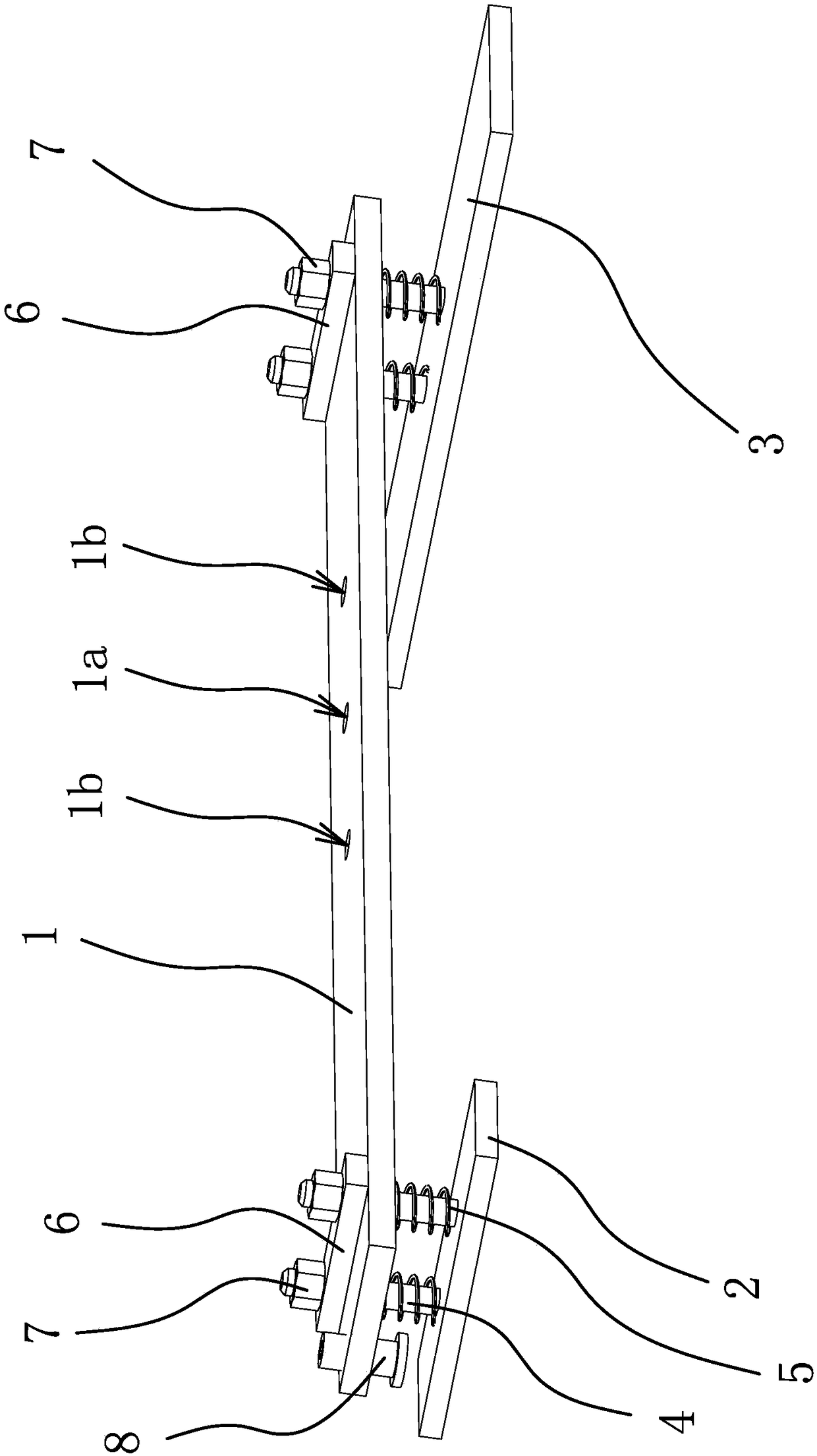
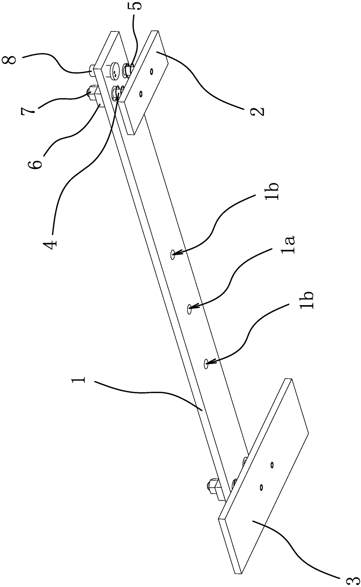
[0027] Such as Figure 1-2 As shown, the cloth transfer mechanism includes a pressing plate connecting plate 1, a front pressing plate 2, a rear pressing plate 3 and two upper pressing plates 6.

[0028]The cloth transfer mechanism is arranged above the worktable, and a drive source is also provided above the workbench. In this embodiment, the drive source is an air cylinder. The middle part of the pressing plate connecting plate 1 is provided with a connecting hole 1a, and the two sides of the connecting hole 1a A guide hole 1b is also provided, the piston rod of the air cylinder is fixedly connected in the connection hole 1a, and a guide shaft is provided on the worktable, and the guide shaft passes through the corresponding guide hole 1b. Both the front pressing plate 2 and the rear pressing plate 3 are located under the pressing plate connecting plate 1 , and the front pressing plate 2 and the rear pressing plate 3 are respectively opposite to the two ends of the pressing ...

Embodiment 2

[0033] The structure of this embodiment is basically the same as that of Embodiment 1, the difference is that the buffer is an elastic sleeve, and the elastic sleeve is sleeved on the guide rod 4, and one end of the elastic sleeve abuts against the pressure plate connecting plate 1 , the other end is against the corresponding front platen 2 or rear platen 3, under the action of the elastic deformation force of the elastic sleeve, the corresponding front platen 2 and rear platen 3 can be produced according to the flatness of the platen, that is, according to the unevenness of the platen The height difference can automatically adjust the initial compression, change the pressure of the front platen 2 or the rear platen 3, so that the front platen 2 or the rear platen 3 always stick to the platen, suitable for fabrics of different thicknesses and flatness is not high The platen keeps the cloth moving smoothly all the time, ensuring that the cloth can enter the follow-up processing ...

Embodiment 3

[0035] The structure of this embodiment is basically the same as that of Embodiment 1, the difference is that the buffer is provided on the surface opposite to the front pressure plate 2 and the pressure plate connecting plate 1, and on the surface opposite to the rear pressure plate 3 and the pressure plate connecting plate 1 One layer of elastic layer made of elastic material, through the elastic deformation capacity of the elastic layer itself, the corresponding front pressure plate 2 and rear pressure plate 3 can be adjusted according to the flatness of the platen, that is, according to the height difference caused by the unevenness of the platen. Automatically adjust the initial compression, change the pressure of the front platen 2 or the rear platen 3, so that the front platen 2 or the rear platen 3 is always attached to the platen, adapt to different thickness of cloth and the platen with low flatness, so that the cloth can be Always maintain smooth transfer to ensure t...


PUM


Abstract

The invention provides a cloth transfer mechanism, belongs to the technical field of machines and solves the problem of low work efficiency of the existing cloth transfer. The cloth transfer mechanism comprises a pressing plate connecting plate, a front pressing plate and a rear pressing plate; each of the front pressing plate and the rear pressing plate is located below the pressing plate connecting plate and is opposite to two ends of the pressing plate connecting plate; each of the front pressing plate and the rear pressing plate is fixedly provided with a vertically-arranged guide rod penetrating through the pressing plate connecting plate; the pressing plate connecting plate can slide along the guide rods to be close to or far away from the front pressing plate and the rear pressing plate; an elastic buffer part is arranged between the front pressing plate and the pressing plate connecting plate; and an elastic buffer part is arranged between the rear pressing plate and the pressing plate connecting plate. The cloth transfer mechanism drives cloth to move in a static friction way, a cloth clamping part is kept not to have drapes and deformation in the transfer process, influences from a height difference caused by unevenness of a deskboard can be avoided, and the cloth can be kept to be transferred smoothly all the time and can be kept to normally enter the subsequent processing and use, so that the work efficiency is increased.

Description

technical field [0001] The invention belongs to the technical field of machinery and relates to a cloth transfer mechanism. Background technique [0002] During the production of textile products, it is often necessary to grip and transfer material from one processing station to another processing station. Many processing manufacturers choose the method of manual feeding, which is not only inefficient but also has hidden dangers in quality. Therefore, the clamping device of the mechanical structure emerges at the historic moment. [0003] The current material transfer method is mostly mechanical arm (or air claw) transfer, which is also widely used in the transfer of cloth. For example, a Chinese patent application (application number: 201410588007.X) discloses a cloth gripper, including upper splint, The lower splint and the connecting assembly; the upper splint and the lower splint cooperate to clamp the objects between them through the connecting assembly; the connectin...

Claims


Application Information

Patent Timeline
Patent Type & Authority Patents(China)
IPC IPC(8): B65H20/16B65H23/34
CPCB65H20/16B65H23/34B65H2301/51256B65H2406/122
Inventor 陈伟强于阳徐涛
Owner JACK SEWING MASCH CO LTD
Learn More