Effluent adjusting canal for artificial wetland

A technology for constructed wetlands and inflow areas, which is applied in marine engineering, water supply installations, water conservancy projects, etc., can solve the problem of unreasonable structural design of water outlet adjustment channels, inability to quantitatively control flow and flow rate, and inability to achieve uniform flow state catchment. and other problems, to achieve the effect of simple and efficient structural design, simple construction machinery, and low cost of building materials

Pending Publication Date: 2017-05-31
LINGNAN LANDSCAPE
View PDF12 Cites 2 Cited by
  • Summary
  • Abstract
  • Description
  • Claims
  • Application Information

AI Technical Summary

Problems solved by technology

[0008] (1) The design of the water outlet adjustment channel is cumbersome, difficult to maintain, and inconvenient to construct
[0009] (2) The structural design of the outlet regulating channel structure is unreasonable, and it is impossible to achieve uniform flow and catchment
[0010] (3) Impurities cannot be intercepted in the outlet water regulation channel, causing a large amount of impurities to deposit in subsequent outlet pipeline facilities, causing blockage and affecting water conservancy conditions
[0011] (4) In the effluent regulating channel, the flow and velocity cannot be quantitatively regulated
[0012] By retrieving domestic and foreign related measures and method literature patents for water regulation of constructed wetlands, it is shown that before the present invention, the same measures and methods for water regulation of constructed wetlands as the present invention have not been reported

Method used


Image

  • Effluent adjusting canal for artificial wetland
  • Effluent adjusting canal for artificial wetland
  • Effluent adjusting canal for artificial wetland

Examples


Embodiment approach

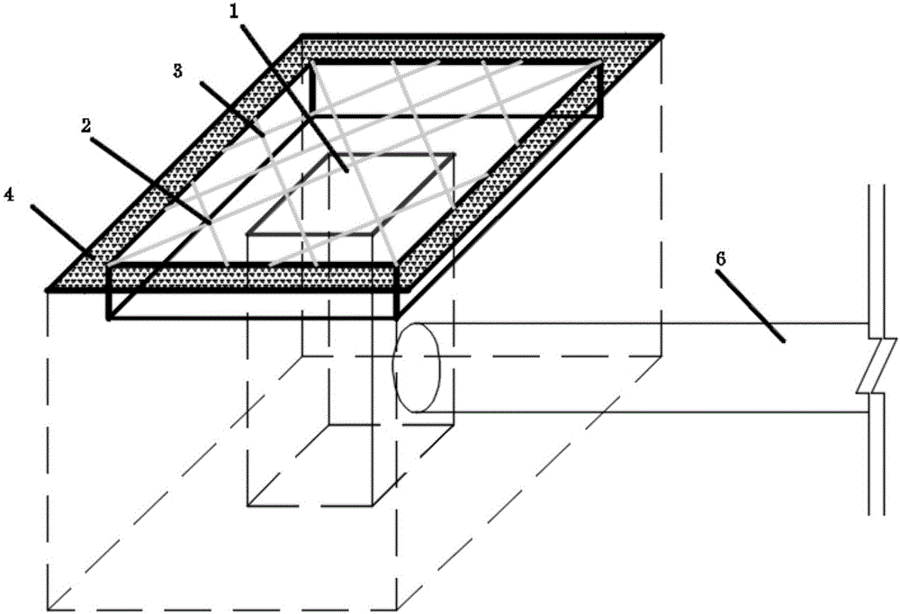
[0043] 1, the site selection of the present invention can be taken near the next processing unit place, do foundation treatment, plain soil under the 100mm sand cushion layer gets final product, build the steel-concrete structure of long 2 meters wide 2 meters high m meters on the foundation, m According to the overall elevation of the constructed wetland, pre-embedded parts are reserved, and the weir teeth 5 are built, the interception grid 3 is installed, and the outlet pipe 6 is installed in sequence.

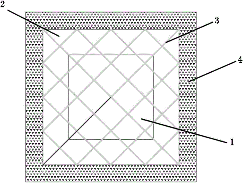
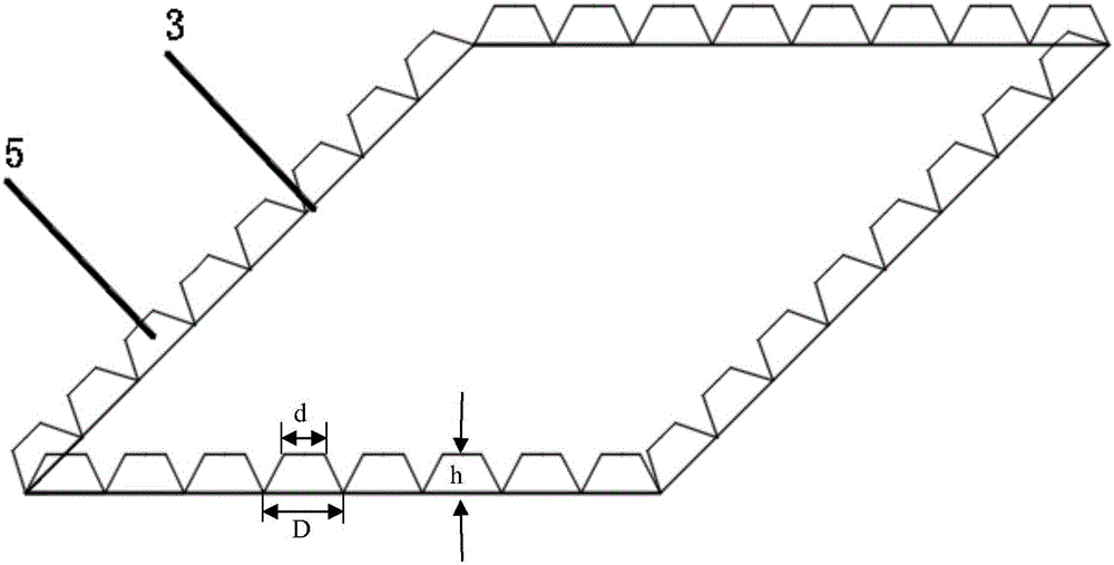
[0044] 2. The construction of water distribution weir 4 can be carried out according to image 3 Carry out, build the weir teeth 5 on the same horizontal plane, the water distribution weir 4 is a reinforced concrete structure, the overall layout is a square, the outer side length is 2.0m, the inner side length is 1.6m, and the width is 200mm. Each of the square water distribution weirs 4 There are 8 weir teeth 5 in the side length, and there are 32 weir teeth 5 in total. Th...


PUM

PropertyMeasurementUnit
diameteraaaaaaaaaa

Abstract

The invention relates to an effluent adjusting canal for an artificial wetland. The effluent adjusting canal for the artificial wetland comprises a water inlet region, an energy dissipation platform, intercepting grid bars and a water distribution weir, wherein the energy dissipation platform is arranged at the outer edge of the water inlet region, the plurality of intercepting grid bars which are arranged in a criss-cross manner are arranged between the upper side of the water inlet region and the lower side of the top end of the water distribution weir; and the water distribution weir is arranged around the energy dissipation platform, and the water distribution weir is higher than the energy dissipation platform. The effluent adjusting canal for the artificial wetland provided by the invention is simple and efficient in structural design and can effectively adjust the effluent quantity and flow rate to achieve a purpose of quantized regulation; the intercepting grid bars are simple in form design, convenient to mount and low in cost price and plays a role of protecting the safety of personnel; and the water distribution weir is designed to replenish water uniformly and stabilize the flow state. The effluent adjusting canal for the artificial wetland is of a steel-concrete composite structure or a brick-concrete structure, so that the effluent adjusting canal for the artificial wetland is simple and convenient to construct and needs not to be managed artificially.

Description

technical field [0001] The invention relates to a water outlet device for artificial wetlands, in particular to a water outlet adjustment device for artificial wetlands. Background technique [0002] In recent years, with the development of society and economy, people's environmental awareness has been continuously enhanced, and higher requirements have been put forward for environmental protection. At the same time, higher requirements have been made for sewage treatment. The "Water Pollution Prevention and Control Action Plan" ("Water Ten Measures") promulgated and implemented by the State Council clearly states that by 2020, the national water environment quality will be improved in stages. By 2030, strive to improve the overall quality of the national water environment and initially restore the functions of the water ecosystem. By the middle of this century, the quality of the ecological environment will be improved in an all-round way, and the ecological system will re...

Claims


Application Information

Patent Timeline
Patent Type & Authority Applications(China)
IPC IPC(8): C02F3/32C02F3/34E02B8/06E03F5/00E03F5/14
CPCE02B8/06E03F5/00E03F5/14C02F3/32C02F3/34C02F2209/40C02F2203/006C02F2209/10Y02W10/10
Inventor 郑冬宇佟镇高彦波徐志郭宏凯王婉清曹大伟于田田王影李远帆
Owner LINGNAN LANDSCAPE
Why Eureka
Try Eureka