Ultrathin glass conveying device

A conveying device, ultra-thin glass technology, applied in glass transportation equipment, glass production, glass manufacturing equipment, etc., can solve the problems of difficulty in accurately measuring the conveying speed of glass plates, difficult to measure by photoelectric sensors, difficult in conveying speed, etc., to reduce the quality defects, improved apparent quality, improved effects of environmental factors

Active Publication Date: 2017-05-31
YICHANG CSG PHOTOELECTRIC GLASS
View PDF6 Cites 1 Cited by
  • Summary
  • Abstract
  • Description
  • Claims
  • Application Information

AI Technical Summary

Problems solved by technology

However, according to the previous record of the plan, "the glass sheet gradually transitions from a softened state to a solid state, and due to the influence of thermal expansion and contraction factors (prime), there is a slight speed change in the forward speed of the glass sheet when it passes through the contact surface of the front and rear adjacent transition rollers." Poor”, that is, the transmission speed of the glass plate is affected by the factors of thermal expansion and contraction, and it is difficult to determine the transmission speed, and the surface of the glass plate is smooth, so it is difficult to use photoelectric sensors to measure it, and other sensors are difficult to accurately measure the transmission speed of the glass plate
Furthermore, the technical means recorded in this patent are also relatively vague, and no solution is given on how to accurately measure the conveying speed of the glass plate at key points, so the realization of this patent is relatively difficult

Method used


Image

  • Ultrathin glass conveying device
  • Ultrathin glass conveying device
  • Ultrathin glass conveying device

Examples


Embodiment Construction

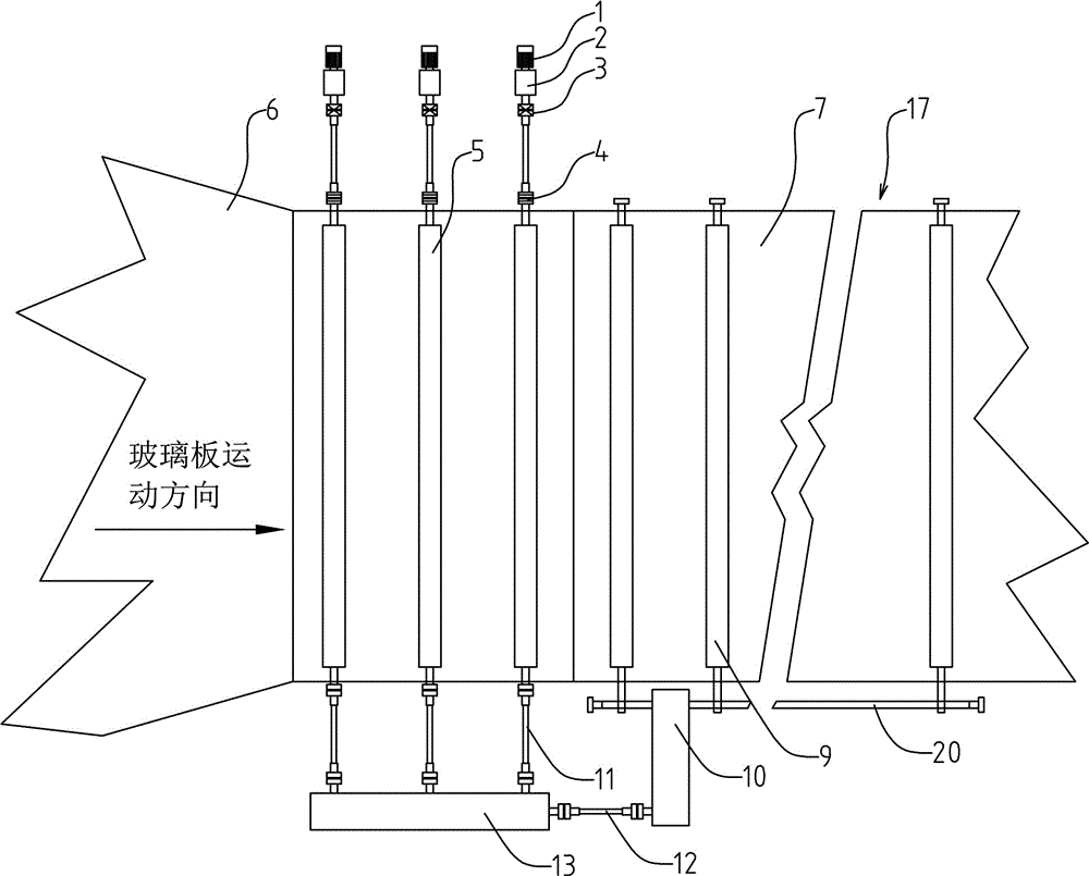
[0028] Such as Figure 1~6 Among them, an ultra-thin glass conveying device includes a plurality of transition rollers 5 located between the tin bath 6 and the annealing furnace 17, the transition rollers 5 are supported on the frame by bearings, and a cooling device is also provided to reduce the working temperature of the bearings. Temperature, one end of a plurality of transition rollers 5 is connected to a driving device through a first transmission mechanism, and the other end of a plurality of transition rollers 5 is connected to a driving device through a second transmission mechanism respectively;

[0029] In the first transmission mechanism described above, the driving device is connected to the deceleration device 10, the deceleration device 10 is fixedly connected to one end of the connecting shaft 12, and the other end of the connecting shaft 12 is connected to a plurality of overrunning clutches 13, and the plurality of overrunning clutches 13 are respectively conn...


PUM

PropertyMeasurementUnit
thicknessaaaaaaaaaa

Abstract

The invention provides an ultrathin glass conveying device which comprises a plurality of transitional rollers located between a tin tank and an annealing kiln. One ends of the plurality of transitional rollers are connected to a driving device through a first transmission mechanism while the other ends of the plurality of transitional rollers are separately connected to the driving device through a second transmission mechanism; in the first transmission mechanism, a speed reducing device is fixedly connected to one end of a connecting shaft while the other end of the connecting shaft is connected to a plurality of overrun clutches, and the plurality of overrun clutches are fixedly connected to the transitional rollers, separately; in the second transmission mechanism, one end of a first coupler is connected to the transitional rollers while the other end of the first coupler is fixedly connected to the speed reducer, and the speed reducer is fixedly connected to a motor. By adopting a scheme of outputting a torque by using a single speed reducing device at one ends of the transitional rollers while outputting torques by the speed reducers at the other ends, separately, the influence caused by errors of automatic control can be overcome to a certain extent by matching with the structures of the overrun clutches, and the quality defects on the lower surface of a glass plate are reduced.

Description

technical field [0001] The invention relates to the field of float ultra-thin electronic glass preparation, in particular to an ultra-thin glass conveying device located between a tin bath and an annealing kiln. Background technique [0002] Ultra-thin electronic glass refers to electronic glass with a thickness of less than 2mm, and further refers to electronic glass within the range of 0.1~1.1mm. At present, customers have higher and higher requirements for the quality of ultra-thin electronic glass, and the slight defects on the surface of ultra-thin electronic glass may cause customer complaints. Especially for the production of high-grade electronic A-level cover glass, the requirements for the apparent quality of the glass are very strict. The number of tin defects on the lower surface needs to be controlled, and there should be no defects such as tin slag printing and scratches. However, in actual production, there is a problem that the transition roller affects the...

Claims


Application Information

Patent Timeline
Patent Type & Authority Applications(China)
IPC IPC(8): C03B35/16
CPCC03B35/163Y02P40/57
Inventor 孙亚明曾庆东张红军
Owner YICHANG CSG PHOTOELECTRIC GLASS
Why Eureka
Try Eureka