Movable anti-disengagement support
An anti-separation and moving body technology, applied in the direction of engine base, supporting machine, pipeline support, etc., can solve the problems of being damaged by the supported body, unable to restrict movement, unable to ensure that the sliding surface of the bearing device is not separated, etc., to facilitate processing. , the effect of improving stability
- Summary
- Abstract
- Description
- Claims
- Application Information
AI Technical Summary
Problems solved by technology
Method used
Image
Examples
Embodiment 1
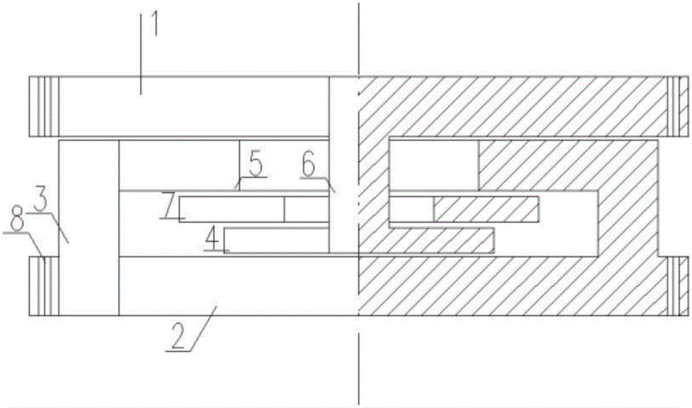
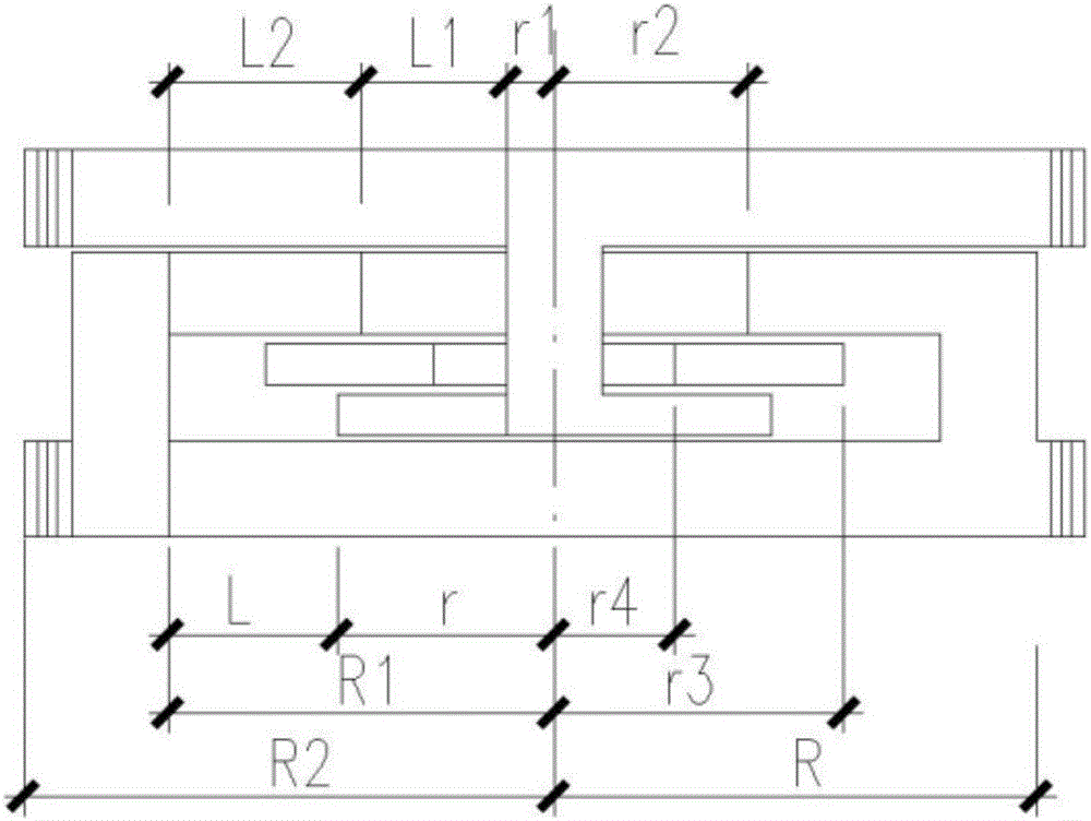
[0054] like figure 1 , figure 2 , Figure 4 , Figure 5 , Image 6 As shown, the upper mobile body 1 and the lower supporting mobile body support have connection holes connected with external objects. Figure 4 It is a schematic diagram of the movement of Example 1 of the present invention under the action of external force; Figure 5 It is a schematic diagram of the displacement of Embodiment 1 of the present invention along the direction perpendicular to the moving direction under the action of external force, or the displacement control amount along the direction perpendicular to the moving direction. Image 6 It is a schematic diagram of the structure of embodiment 1 when it is inverted, and other components are also inverted correspondingly at this time. Figure 8 , Figure 9 , Figure 10 is a top view of the structural member. Figure 9 The middle anti-disengagement connector 6 and the lower anti-disengagement moving body 4 are integral components. like figu...
Embodiment 2
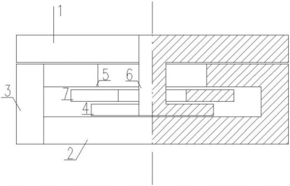
[0065] like image 3 , Figure 7 As shown, between the upper moving plate 1 and the lower supporting moving body 2, the lower supporting moving body 2 is connected with a controlled moving block 3 and an upper anti-disengagement controlled moving body 5, and the upper moving body 1 is connected with an anti-disengagement connector 6 and The lower anti-separation moving body 4 and the middle anti-separation connecting piece 6 pass through the upper anti-separation control moving body 5 and the anti-separation plate 7. One end of the control mobile blocking body 3 is connected with the lower support mobile body 2, and one end is connected with the upper anti-disengagement control mobile body 5, and supports the upper mobile body 1. Figure 7 It is a schematic diagram of the movement of Example 2 of the present invention under the action of external force.
PUM
 Abstract
Description
Claims
Application Information
 - R&D
- Intellectual Property
- Life Sciences
- Materials
- Tech Scout
- Unparalleled Data Quality
- Higher Quality Content
- 60% Fewer Hallucinations
Browse by: Latest US Patents, China's latest patents, Technical Efficacy Thesaurus, Application Domain, Technology Topic, Popular Technical Reports.
© 2025 PatSnap. All rights reserved.Legal|Privacy policy|Modern Slavery Act Transparency Statement|Sitemap|About US| Contact US: help@patsnap.com


