Road facility utilizing piezoelectric power generation based detachable oscillating deceleration warning device

A piezoelectric power generation and warning device technology is applied in the field of pavement facilities of a detachable oscillating deceleration warning device. The effect of driving safety and improving economic efficiency

Active Publication Date: 2017-05-31
合肥庐阳科技创新集团有限公司
View PDF11 Cites 1 Cited by
  • Summary
  • Abstract
  • Description
  • Claims
  • Application Information

AI Technical Summary

Problems solved by technology

[0004] The "bulge" of the oscillating markings and speed bumps causes the energy loss of the vehicle. The on-site construction process requires a large area of ​​closed traffic and a large amount of manpower to complete. The ambient temperature of the marking construction is generally required to be no lower than 5°C, and the construction accuracy is poor and The speed is slow, and the construction process is accompanied by high-temperature heating of hot-melt coatings, which has certain safety hazards; at the same time, because the "raised" parts of the two traffic safety facilities are extremely easy to wear, the microbeads on the oscillating marking lines are also easy to wear and slip
After the speed bump is damaged, it is generally maintained by replacing and reinstalling it as a whole. After the vibration marking is damaged, it is often maintained by a small marking milling machine and then re-constructed. The process is complicated and the cost is high.

Method used


Image

  • Road facility utilizing piezoelectric power generation based detachable oscillating deceleration warning device
  • Road facility utilizing piezoelectric power generation based detachable oscillating deceleration warning device
  • Road facility utilizing piezoelectric power generation based detachable oscillating deceleration warning device

Examples


Embodiment Construction

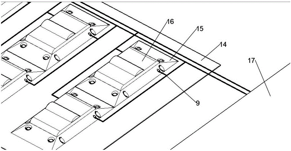
[0048] see figure 1 , the structural form of the detachable vibration deceleration warning device based on piezoelectric power generation in this embodiment is: the vibration deceleration warning device is set as an assembled modular structure, and the substrate 14 is fixedly installed on the road surface, and the vibration modules 16 are arranged in rows and columns. On the base plate 14, there is an interval between the oscillation modules of adjacent rows and adjacent columns, and each oscillation module 16 is independently installed on the base plate 14 through the base plate 15 to form a detachable oscillation deceleration warning device; in the oscillation module 16 The piezoelectric generating piece 4 is arranged in the middle to form a power generation oscillation module, and the deformation of the piezoelectric generating piece 4 is driven by the pressure deformation of the power generation oscillation module, thereby generating electric energy; the surface of the osci...


PUM


Abstract

The invention discloses a road facility utilizing piezoelectric power generation based detachable oscillating deceleration warning device. The device is characterized in that the oscillating deceleration warning device is set as an assembled modular structure, to be specific, a base plate is fixedly mounted on the road surface, the oscillation modules are arranged in ranks on the base plate, the oscillation module of adjacent rows are separated from the oscillation module of adjacent lists, each oscillation module is independently mounted on the base plate by base plate screws to form the detachable oscillation deceleration warning device; further, a piezoelectric power generation sheet is set in the oscillation module to form a power generation oscillation module, the piezoelectric power generation sheet deformation is driven by the power generation oscillation module of compression deformation, and thus power generation is generated. The road facility based the detachable oscillation deceleration warning device makes full use of idle energy of road facilities to produce relatively stable electric power; the road facility can be detached partially or integrally without damaging the original structure of the road surface, thereby bringing convenience to construction and maintenance.

Description

technical field [0001] The invention relates to a road facility of an oscillation deceleration warning device applied on the road, more specifically a road facility based on a detachable oscillation deceleration warning device based on piezoelectric power generation. Background technique [0002] Oscillating markings, speed bumps, etc. are necessary road traffic safety facilities on various roads. [0003] In the prior art, the oscillating markings are protrusions on the road surface formed by marking paint mixed with reflective glass beads, which play the role of warning and forced deceleration. The shape of the speed bump is generally strip or dot, with yellow and black to attract visual attention, so that the road surface is slightly arched to achieve the purpose of vehicle deceleration. Slow road sections and road sections that are prone to traffic accidents. [0004] The "bulge" of the oscillating markings and speed bumps causes the energy loss of the vehicle. The on-...

Claims


Application Information

Patent Timeline
Patent Type & Authority Applications(China)
IPC IPC(8): E01F9/529H02N2/18
CPCH02N2/186
Inventor 刘凯黄浩亮陈传琪袁淼张旗余航陆添阳疏醒徐先明戴冬凌
Owner 合肥庐阳科技创新集团有限公司
Why Eureka
Try Eureka