Combined reinforcement continuous wall and construction method thereof

A construction method and reinforcement technology, which are applied in excavation, sheet pile wall, foundation structure engineering, etc., can solve the problems of high requirements for construction personnel, large pollution of external mud, and high cost of mud discharge, and improve construction conditions and construction. impact, superior structural ductility performance, and the effect of reducing engineering costs

Active Publication Date: 2017-05-31
王立明
View PDF6 Cites 1 Cited by
  • Summary
  • Abstract
  • Description
  • Claims
  • Application Information

AI Technical Summary

Problems solved by technology

The concrete underground diaphragm wall has the advantages of high bending rigidity, small deformation of the foundation pit, and high safety, but on the other hand, it also has disadvantages such as high engineering cost, slow construction speed, complicated process, high difficulty, and large mud pollution.
The concrete underground diaphragm wall is not only complicated in construction technology, but also has higher requirements for construction personnel, and will generate a large amount of waste mud
In big cities, the cost of mud drainage is getting higher and higher and the trend is getting stronger, and the current mud drainage in big cities such as Shanghai is not only a problem of high cost, but also a problem of nowhere to go.

Method used


Image

  • Combined reinforcement continuous wall and construction method thereof
  • Combined reinforcement continuous wall and construction method thereof
  • Combined reinforcement continuous wall and construction method thereof

Examples


Embodiment 1

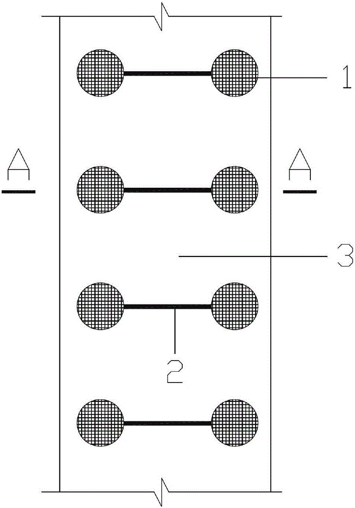
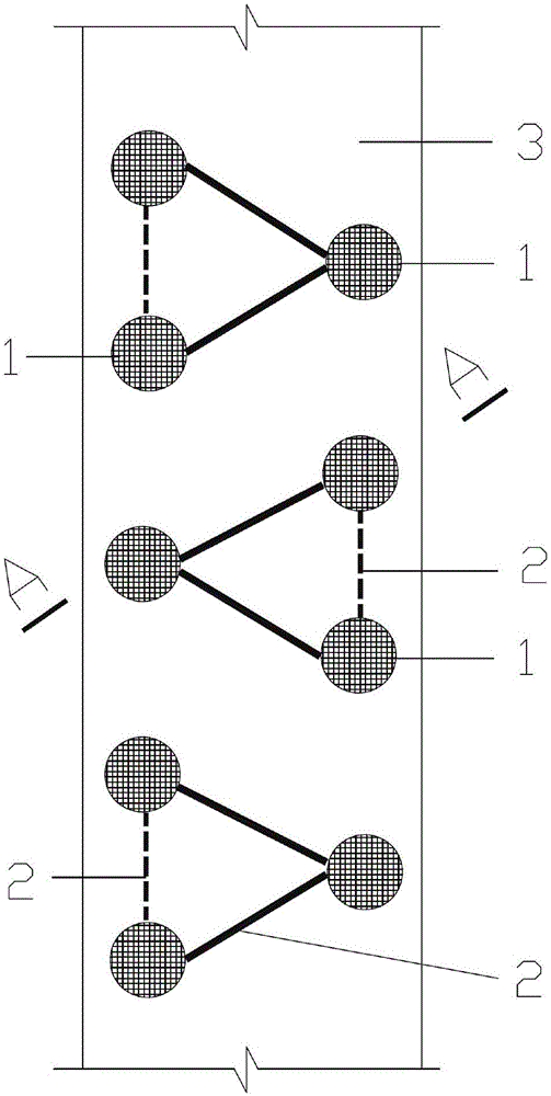
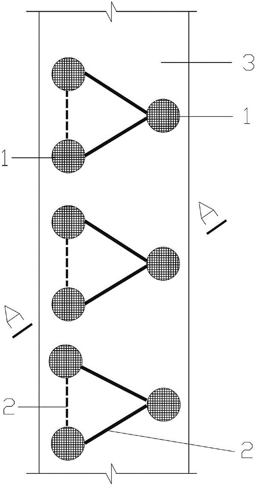
[0077] Step 1: (see Figure 1 to Figure 17 shown) as described above to make composite reinforcements.

[0078] The second step: make cement and soil external auxiliary materials according to the above construction.

[0079] Step 3: Quickly insert the combined reinforcement to the predetermined position before the initial setting of the cement and soil.

[0080] Step 4: Fill in the inner filler according to the construction method mentioned above, and the body crown can be removed and reused after the outer auxiliary material is condensed.

[0081] Step 5: After the external auxiliary material and the internal filling material are condensed and reach the set age, the continuous wall of the combined reinforcement is formed.

Embodiment 2

[0083] The first step: with embodiment 1.

[0084] The second step: make lime soil external accessories according to the above construction.

[0085] Step 3: Before the initial setting of the lime-soil slurry, quickly insert the combined reinforcement to the predetermined position.

[0086] The fourth step: with embodiment 1.

[0087] Step 5: Same as Example 1.

Embodiment 3

[0089] The first step: with embodiment 1.

[0090] The second step: make lime soil external accessories according to the above construction.

[0091] Step 3: before the initial setting of the lime-soil slurry, quickly insert the combined reinforcement to the predetermined position, and mix sand and stone into the lime-soil slurry to form the external auxiliary material of composite clay.

[0092] The fourth step: with embodiment 1.

[0093] Step 5: Same as Example 1.


PUM


Abstract

The invention relates to a combined reinforcement continuous wall and belongs to the technical field of foundation pit support in civil engineering. The combined reinforcement continuous wall can replace a concrete underground continuous wall support mode and a bored concrete pile support mode. The combined reinforcement continuous wall is composed of vertical reinforcements, connection bodies, multifunctional crowns, inner charged materials and outer auxiliary materials. Each vertical reinforcement is composed of a pipe body or formed after the pipe body is combined with a linear body, wherein the linear body is located in the pipe body. Each connecting body is composed of a horizontal component or a vertical component or an inclined component or a plate provided with holes. The crowns are located on the tops of the vertical reinforcements and can be assembled, detached and repeatedly used. After the connecting bodies and the crowns are connected with the vertical reinforcements, a combined reinforcement is formed. The inner charged materials are located in the pipe bodies. The outer auxiliary materials are located outside the pipe bodies. The invention further relates to a construction method of the combined reinforcement continuous wall. When applied to foundation pit support, the combined reinforcement continuous wall and a construction method of the combined reinforcement continuous wall have the advantages that cost can be reduced, the work efficiency can be improved, the safety can be improved, and environmental friendliness can be achieved.

Description

technical field [0001] The invention relates to an underground diaphragm wall for foundation pit protection in the technical field of foundation pit engineering in civil engineering, in particular to a diaphragm wall with combined reinforcement and a construction method thereof. Background technique [0002] At present, in the foundation pit enclosure (also known as foundation pit support) engineering of construction engineering in civil engineering and other projects, the enclosure wall used to retain soil and water on the side wall of the pit is usually a steel cement-soil continuous wall and Concrete underground diaphragm wall. Since the shaped steel cement-soil continuous wall is leased, the cost is related to the construction period, and it is not the technical scope and type of the comparison of the present invention. The concrete underground diaphragm wall has the advantages of high bending rigidity, small deformation of the foundation pit, and high safety, but on th...

Claims


Application Information

Patent Timeline
IPC IPC(8): E02D5/20E02D17/04
CPCE02D5/20E02D17/04E02D2300/0006E02D2300/0018E02D2300/0026E02D2300/0029
Inventor 王立明
Owner 王立明
Why Eureka
Try Eureka