Eureka AIR delivers breakthrough ideas for toughest innovation challenges, trusted by R&D personnel around the world.

A connection node between an h-shaped steel beam and a rectangular steel tube concrete column and its manufacturing method

A technology of rectangular steel tube and concrete column, applied in the direction of building, building structure, etc., can solve the problems affecting the overall mechanical performance of the rectangular steel tube concrete column, the influence of the compact core concrete, the difficulty of pouring the core concrete, etc., so as to optimize the welding construction. method, the effect of reducing construction complexity and reliable construction quality

Active Publication Date: 2017-11-10
SHANDONG UNIV OF SCI & TECH
View PDF5 Cites 0 Cited by
  • Summary
  • Abstract
  • Description
  • Claims
  • Application Information

AI Technical Summary

Problems solved by technology

However, due to the limitation of the side length of the pipe column, the existing inner diaphragm connection node with a hole in the middle makes it difficult to pour the core concrete and inconvenient to vibrate, which affects the compactness of the core concrete pouring and the constraints on the core concrete. large impact, thus affecting the overall mechanical performance of the rectangular concrete filled steel tube column
[0006] In the existing manufacturing method of the inner partition type rectangular steel tube concrete column, the inner partition is usually connected with the rectangular steel tube column by the "melting nozzle electroslag welding" method, the construction is complicated and the cost is high

Method used


Image

  • A connection node between an h-shaped steel beam and a rectangular steel tube concrete column and its manufacturing method
  • A connection node between an h-shaped steel beam and a rectangular steel tube concrete column and its manufacturing method
  • A connection node between an h-shaped steel beam and a rectangular steel tube concrete column and its manufacturing method

Examples


Embodiment Construction

[0047] In conjunction with the accompanying drawings of the embodiments, the present invention is described in detail:

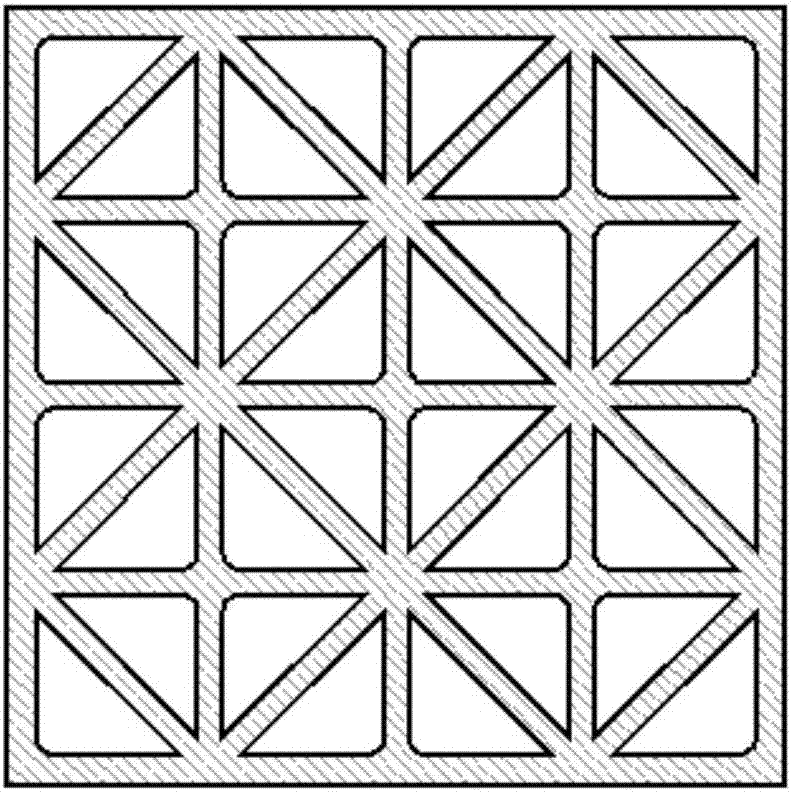
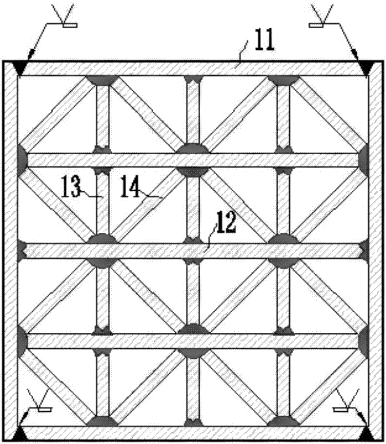
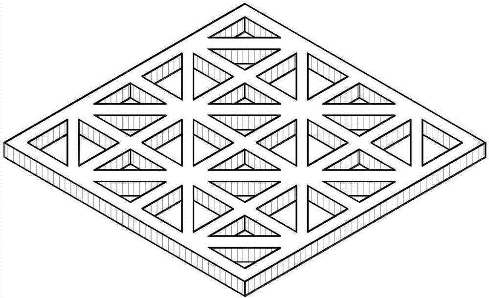
[0048] like Figure 1 to Figure 7 As shown, a connection node between an H-shaped steel beam and a rectangular steel tube concrete column is composed of a rectangular steel tube concrete column, an H-shaped steel beam and connecting force transmission components.

[0049] The rectangular steel pipe concrete column is formed by pouring core concrete 6 in a rectangular steel pipe 1, wherein the rectangular steel pipe 1 is formed by connecting four wall plates 1a, 1b, 1c and 1d in a certain welding order.

[0050] The inner wall of the rectangular steel pipe concrete column is welded with upper and lower mesh inner partitions distributed on the upper and lower sides, and the upper and lower mesh inner partitions are parallel to each other; H-shaped steel beams 2 are connected to the outer wall of the rectangular steel pipe concrete column. : The vertical conne...


PUM


Abstract

The invention discloses a connection node between an H-shaped steel beam and a rectangular steel pipe concrete column and a manufacturing method thereof. It consists of rectangular steel tube concrete columns, H-shaped steel beams and connecting force-transmitting parts, which include upper-grid inner partitions, lower-grid inner partitions and web connecting plates. The inner wall of the rectangular steel pipe concrete column is respectively welded with upper and lower grid inner partitions distributed up and down, and the upper and lower grid inner partitions are parallel to each other. H-shaped steel beams are connected to the outer wall of the rectangular steel tube concrete column: the vertical connecting plate is located on the web of the H-shaped steel beam, welded to the outer wall of the rectangular steel tube concrete column and connected to the web of the H-shaped steel beam by bolts; The upper and lower flanges of the beam are respectively welded to the outer wall of the rectangular steel pipe concrete column; ensure that the upper flange of the grid-type internal partition and the H-shaped steel beam are at the same horizontal position, and the lower grid-shaped internal partition and the lower wing of the H-shaped steel beam The edges are at the same horizontal position to achieve reliable transmission of force.

Description

technical field [0001] The invention belongs to the field of building engineering, and in particular relates to building structure technology, in particular to a connection node between an H-shaped steel beam and a rectangular steel pipe concrete column and a manufacturing method. Background technique [0002] With the development of building structures, the research and application of steel-concrete composite structures has been rapidly developed. The steel pipe concrete column structure is composed of steel pipes filled with concrete. The existence of steel pipes can restrain the core concrete and prevent the core concrete from being overstressed. Early cracking; the existence of core concrete can prevent premature buckling of steel pipes, and the synergistic effect of the two can give full play to the advantages of high tensile performance of steel and good compression performance of core concrete, so it has high bearing capacity, good plasticity and toughness, and seismic...

Claims


Application Information

Patent Timeline
Patent Type & Authority Patents(China)
IPC IPC(8): E04B1/18E04B1/58
CPCE04B1/185
Inventor 王来陈惠荣董硕陈海涛玄伟
Owner SHANDONG UNIV OF SCI & TECH
Why Eureka
Eureka Blog
Learn More