
A sunshade device

A sunshade and substrate technology, applied in the field of sunshades, can solve the problems of poor stability of the support seat, shaking or even blowing over, potential safety hazards, etc., and achieve the effects of reducing occupied space, labor-saving and easy operation, and improving installation speed

Active Publication Date: 2018-12-18
常熟市常盛新型建材有限公司
View PDF6 Cites 0 Cited by
  • Summary
  • Abstract
  • Description
  • Claims
  • Application Information

AI Technical Summary

Problems solved by technology

[0002] The use of awnings is becoming more and more widespread. Its main function is to shade the sun and reduce the temperature. However, the awning needs to have a certain height when it is installed. The existing setting of the awning is generally spliced ​​by two or more supporting rods. After the ideal support height is reached, the installation and disassembly process is cumbersome and the efficiency of installation and disassembly is low after being fastened and connected by screws. At the same time, the support seat of the existing medium awning has poor stability when supported, and it is extremely difficult to withstand windy weather. It is easy to shake or even blow over, which causes economic losses to people and also has great potential safety hazards

Method used


Image

  • A sunshade device
  • A sunshade device
  • A sunshade device

Examples


Embodiment Construction

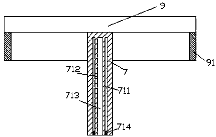
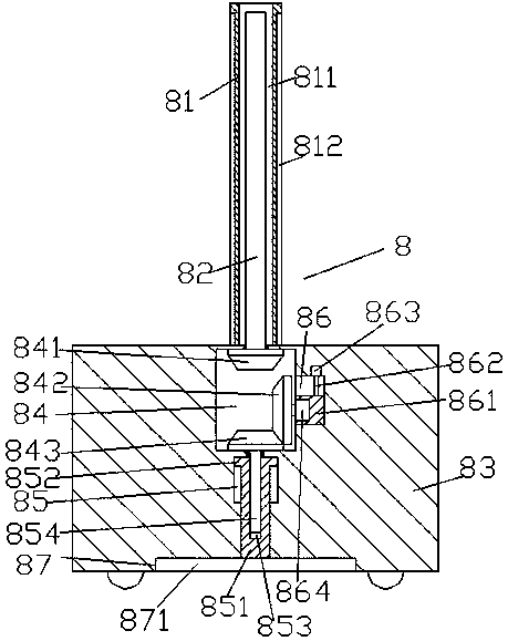
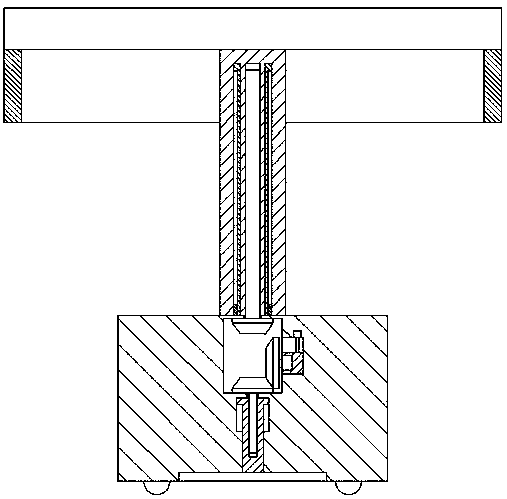
[0020] Such as Figure 1-Figure 6 As shown, an awning device of the present invention includes an upper base 7, a lower base 8, and an awning 9 fixedly arranged on the top of the upper base 7, and the outer circumference of the bottom end surface of the awning 9 is provided with a downward extending The sunshade 91, the sunshade 91 is used to better shield the sun, the upper base 7 is provided with a downwardly extending first cavity 711, and the top middle of the first cavity 711 is set There is a first sleeve 712 extending downward, and a first inner threaded cavity 713 is provided in the first sleeve 712, and the lower base 8 is extended upward and enters the first cavity 711 The second sleeve 81 is composed of the second sleeve 81 and the base 83 arranged at the bottom of the second sleeve 81. The outer walls of the left and right sides of the second sleeve 81 are respectively provided with first sliding grooves 812. The second sleeve 81 is provided with a second cavity 8...


PUM


Abstract

The invention discloses an awning device which comprises an upper base body, a lower base body and an awning fixedly arranged on the top of the upper base body. An awning curtain extending downwards is arranged around the bottom end face of the awning. A first containing cavity extending downwards is arranged inside the upper base body. A first sleeve extending downwards is arranged in the middle of the top inside the first containing cavity. A first internal threaded cavity is arranged inside the first sleeve. The lower base body is formed by a second sleeve which extending upwards and entering the first containing cavity and a base arranged at the bottom of the second sleeve, the outer walls of the left and right sides of the second sleeve are correspondingly provided with first slip grooves, a second containing cavity for being connected with the first sleeve in a slip fit mode is arranged inside the second sleeve, and the bottoms of the inner walls of the two sides of the first containing cavity are correspondingly provided with guiding blocks which enter the first slip grooves and are connected with the first slip grooves in a slip fit mode. The awning device is simple in structure, convenient to operate, capable of being automatically controlled to be lifted and supported stably, convenient to install and capable of improving the using safety.

Description

technical field [0001] The invention relates to the technical field of awnings, in particular to an awning device. Background technique [0002] The use of awnings is becoming more and more widespread. Its main function is to shade the sun and reduce the temperature. However, the awning needs to have a certain height when it is installed. The existing setting of the awning is generally spliced ​​by two or more supporting rods. After the ideal support height is reached, the installation and disassembly process is cumbersome and the efficiency of installation and disassembly is low after being fastened and connected by screws. At the same time, the support seat of the existing medium awning has poor stability when supported, and it is extremely difficult to withstand windy weather. It is easy to shake or even blow over, and it also has a greater potential safety hazard while causing economic losses to people. Contents of the invention [0003] The technical problem to be so...

Claims


Application Information

Patent Timeline
Patent Type & Authority Patents(China)
IPC IPC(8): E04H1/12
CPCE04H1/1205
Inventor 范全有
Owner 常熟市常盛新型建材有限公司
Learn More