Variable-diameter stabilizer

A stabilizer and variable technology, applied in the direction of drill pipe, casing, drill pipe, etc., can solve problems such as increased risk of collapse, long operation cycle, stuck pipe, etc., to reduce the risk of collapse, save tripping time, reduce Effect of Soaking Time

Active Publication Date: 2017-05-31
BC P INC CHINA NAT PETROLEUM CORP +1
View PDF6 Cites 2 Cited by
  • Summary
  • Abstract
  • Description
  • Claims
  • Application Information

AI Technical Summary

Problems solved by technology

The traditional drilling operation uses a stabilizer with a fixed outer diameter, which requires at least three trips to install/replace the stabilizer, resulting in different drilli...

Method used


Image

  • Variable-diameter stabilizer
  • Variable-diameter stabilizer
  • Variable-diameter stabilizer

Examples


Embodiment 1

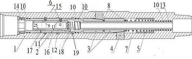
[0033] This embodiment provides a variable-diameter stabilizer, including a cylindrical housing 1, the inner wall of the housing 1 is provided with at least a first housing lock ring groove 11, a second housing lock ring groove 11, and a second housing lock ring groove from top to bottom. The ring groove 19 is two shell lock ring grooves, the housing 1 is provided with a piston 2, the piston 2 is a hollow structure, the upper end of the piston 2 is provided with a pressure cap 14, and the upper part of the piston 2 is provided with a A sliding sleeve 16 that can move axially along the piston 2. The outer surface of the piston 2 is provided with a card shaft 17, a first lock shaft 6, and a second lock shaft 15 in sequence from top to bottom. The first lock shaft 6, the second lock shaft The two locks 15 are multiple and evenly distributed in the circumferential direction. The outer surface of the lower part of the piston 2 is provided with a plurality of conical sleeves 3 from t...

Embodiment 2

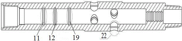
[0040] On the basis of embodiment 1, this embodiment provides a kind of figure 1 In the shown variable diameter stabilizer, the inner wall of the housing 1 is provided with a first housing lock ring groove 11, a third housing lock ring groove 12, and a second housing lock ring groove from top to bottom. 19. The lock ring groove 11 of the first housing, the lock ring groove 12 of the third housing and the lock ring groove 9 of the first sliding sleeve are all matched with the first lock ring 6, and the lock ring groove of the second housing is Both the ring groove 19 and the ring groove 13 of the second sliding sleeve lock are matched with the second lock 15;

[0041] The first sliding sleeve lock ring groove 9, the first lock ring groove 6, the first housing lock ring groove 11, the third housing lock ring groove 12, the second sliding sleeve lock ring groove 13, the second The distances between the lock shaft 15 , the second housing lock shaft ring groove 19 and the top of t...

Embodiment 3

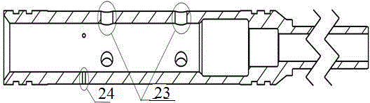
[0047] On the basis of Embodiment 2, this embodiment provides a variable-diameter stabilizer, the piston 2 is a hollow structure with a large inner diameter and a small bottom, and the lower part of the piston 2 is sleeved with a plurality of tapered sleeves 3 Smaller inner diameter. Both ends of the large diameter part are provided with seals 10, and the structure of the piston 2 is as follows: image 3 shown.

[0048] One end of the sliding sleeve 16 is provided with a Kashaw groove 25 , and the other end is provided with a discharge hole 27 and a ball-throwing blocking shoulder 26 sequentially from top to bottom. The liquid flow channel of the sliding sleeve 16 is opened, and the liquid flows out through the discharge hole 27 .

[0049] Such as Image 6 As shown, the centralizing column 4 is columnar, one end surface is a cylindrical surface, and the other end is a conical plane matched with the conical surface of the conical surface sleeve 3. The conical surface is prov...


PUM


Abstract

The invention provides a variable-diameter stabilizer which comprises a shell, a piston, a slide sleeve, a cone sleeve and a righting column. The cone sleeve is arranged on the lower portion of the piston, the righting column is arranged on the shell, and the cone sleeve and the righting column are matched with each other, so that the diameter can vary. The variable-diameter stabilizer has the advantages that the variable-diameter stabilizer can be controlled from the ground, so that the purpose of varying the diameter can be achieved; balls are cast to wellheads repeatedly, and accordingly the drafting purposes can be achieved by the aid of different drilling tool combinations without tripping out when the corresponding stabilizer is in rolling-out states; only drilling strings need to be tripped out to casing legs when double-support or triple-support drafting needs to be carried out, the balls can be cast, the righting column of the double-support (or triple-support) drafting variable-diameter stabilizer can stretch out under the control, and single-support, double-support and triple-support drafting can be carried out; the trip-out time can be saved when the stabilizer is used, the well wall soaking time can be shortened, downhole collapse risks can be reduced, and the drafting efficiency can be improved.

Description

technical field [0001] The invention belongs to the technical field of drilling operation equipment, and in particular relates to a variable-diameter stabilizer. Background technique [0002] In horizontal well operations, in order to ensure that the wellbore is unobstructed when running the casing, it is necessary to carry out drilling operations before running the casing. Generally, single-supported, double-supported and three-supported drilling tools are used for three times of drilling. Traditional drilling operations use a stabilizer with a fixed outer diameter, which requires at least three trips to install / replace the stabilizer, resulting in different drill tool combinations. The operation cycle is long, and it is easy to cause obstruction and pipe sticking. At the same time, due to the long-term immersion of the well wall, the risk of collapse increases. Contents of the invention [0003] The purpose of the present invention is to overcome the above-mentioned pr...

Claims


Application Information

Patent Timeline
IPC IPC(8): E21B17/10
CPCE21B17/1014
Inventor 杨森李晓明薛让平李录科陈霖高峰伟陈伟林
Owner BC P INC CHINA NAT PETROLEUM CORP
Why Eureka
Try Eureka