Air foam flooding oil-extraction well site device and air foam flooding oil-extraction well site technology

A technology for air foam flooding and oil production, which is applied in the fields of fluid production, earth-moving drilling, wellbore/well components, etc., can solve the problems of high labor intensity and potential safety hazards, and achieve simple construction, process optimization, safe and environmentally friendly operation. Effect

Active Publication Date: 2017-05-31
XIAN CHANGQING TECH ENG
View PDF17 Cites 4 Cited by
  • Summary
  • Abstract
  • Description
  • Claims
  • Application Information

AI Technical Summary

Problems solved by technology

[0005] The purpose of the present invention is to overcome the technical problems of high labor intensity and potential safety hazards for air foam flooding personnel, and to provide an air foam flooding well site device and its craft

Method used


Image

  • Air foam flooding oil-extraction well site device and air foam flooding oil-extraction well site technology
  • Air foam flooding oil-extraction well site device and air foam flooding oil-extraction well site technology

Examples


Embodiment 1

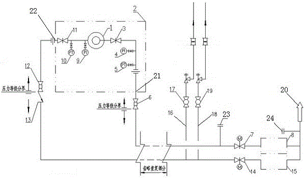
[0035] In order to overcome the technical problems of high labor intensity and potential safety hazards for air foam flooding personnel, this embodiment provides a method such as figure 1 and figure 2The shown air foam flooding oil production well site device and its technology, the oil production wellhead 1 is connected to the oil production tree 2, the oil pipe outlet 21 and the casing gas outlet 22 are arranged on the oil production wellhead 1, the oil pipe and the oil pipe outlet of the oil production wellhead 1 21 is connected, the oil pipe outlet 21 is connected to the well site ball throwing device area 8 through the pipeline, the casing of the oil production wellhead 1 is connected with the casing gas outlet 22, and the casing gas outlet 22 is connected to the casing gas constant pressure degassing area 15 through the pipeline, The wellsite ball throwing device area 8 is connected to the casing gas constant pressure release area 15 through pipelines and leads to the o...

Embodiment 2

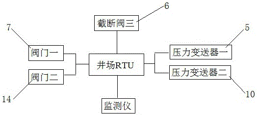
[0044] On the basis of Embodiment 1, this embodiment provides an air foam flooding oil production well site device and its technology. A shut-off valve 1 3 and a pressure gauge 1 4 are arranged between them, and a pressure gauge 2 9 and a shut-off valve 2 11 are arranged in sequence between the casing of the oil production wellhead 1 and the casing gas outlet 22.

[0045] The first shut-off valve 3 and the second shut-off valve 11 are manual shut-off valves, which can be manually closed when the device is abnormal. The cut-off valve 3 6 adopts a high-low pressure emergency cut-off valve with an electric actuator, which can not only sense the pipeline pressure through the pressure pipe of the valve body, automatically shut down, but also shut down through the command sent by the signal line. The cut-off valve 412 adopts a mechanical high-low pressure emergency cut-off valve, which senses the pipeline pressure through the pressure-taking pipe of the valve body, and automatically...


PUM


Abstract

The invention provides an air foam flooding oil-extraction well site device and an air foam flooding oil-extraction well site technology. A first pressure transmitter is arranged between an oil extraction wellhead and an oil tubing outlet, a second pressure transmitter is arranged between an oil extraction wellhead and a casing gas outlet, a third intercepting valve and a first valve are sequentially arranged on a pipeline between the oil tubing outlet and a well site pitching device, a fourth intercepting valve, a check valve and a second valve are sequentially arranged on a pipeline between the casing gas outlet and a casing gas constant-pressure gas release area, and the first pressure transmitter, the third intercepting valve, the first valve, the second pressure transmitter and the second valve are electrically connected to a well site RTU. The air foam flooding oil-extraction well site device and the air foam flooding oil-extraction well site technology have the advantages that through a normal production process, a gas channeling generation process, a safety emptying process and an oxygen content monitoring process, production safety is ensured, safety, high automation degree and environment protection are achieved, the technical problems that air foam flooding personnel is high in operation labor intensity and potential safety hazard are solved, and accordingly the device and the technology are promising in application prospect for test or oil fields employing enhanced oil recovery.

Description

technical field [0001] The invention relates to the application of air foam flooding technology in oil and gas field surface engineering, in particular to an air foam flooding well site device and its technology. Background technique [0002] Changqing Oilfield is a typical ultra / ultra-low permeability reservoir with poor physical properties, strong heterogeneity, developed micro-fractures, and high original gas-oil ratio. After the air foam flooding technology is tested in the oil area, there is a high risk of gas channeling, especially in the intensified area. It is predicted that the gas-oil ratio after gas channeling can reach 500m 3 / t or more; once gas channeling occurs, it will seriously threaten the safety of the ground gathering and transportation pipeline network and downstream oil and gas gathering and transportation stations. [0003] At the same time, many factors, such as unclear oxygen consumption in the reservoir, unclear migration and accumulation direction...

Claims


Application Information

Patent Timeline
Patent Type & Authority Applications(China)
IPC IPC(8): E21B43/22E21B43/12E21B47/00E21B47/06E21B47/117E21B35/00
CPCE21B35/00E21B43/12E21B43/166E21B47/00E21B47/06E21B47/117
Inventor 翟博文胡建国张小龙白剑锋王荣敏穆冬玲王博张园刘晓丽谢晋
Owner XIAN CHANGQING TECH ENG
Why Eureka
Try Eureka