Intelligent analysis and decision-making system and method for oil well failure
A decision-making system and fault technology, applied in the fields of prediction, oil well fault intelligent analysis decision-making system and diagnosis, oil well fault intelligent analysis and decision-making system, and decision-making scheme, can solve problems such as hidden safety hazards, time-consuming and labor-intensive work, and low work efficiency
- Summary
- Abstract
- Description
- Claims
- Application Information
AI Technical Summary
Problems solved by technology
Method used
Image
Examples
Embodiment 1
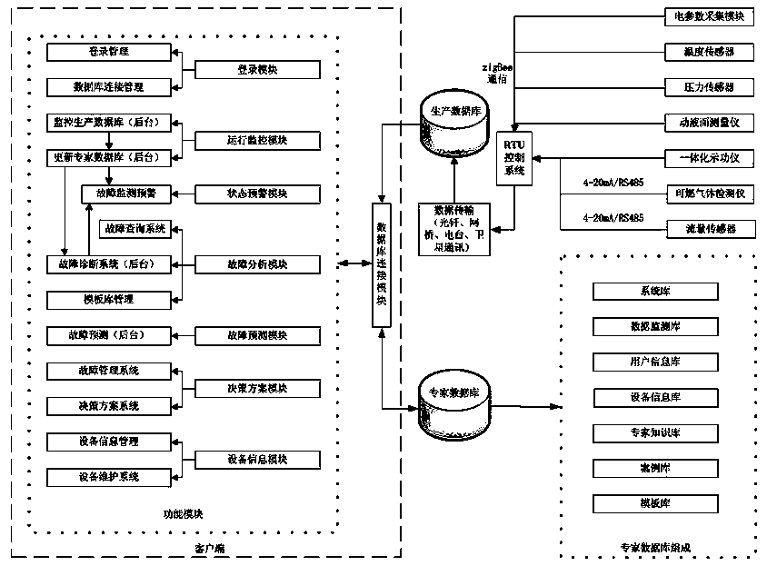
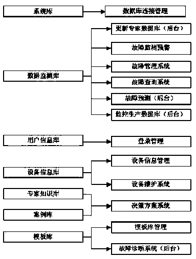
[0098] Embodiment 1: as attached figure 1 , 2 As shown, the oil well fault intelligent analysis and decision-making system includes a data acquisition module, a remote measurement and control module, a server, a database connection module and a function module. The data acquisition module includes an electrical parameter acquisition module, a temperature sensor, a pressure sensor, a dynamic liquid level measuring instrument, Chemical dynamometer, flow sensor and combustible gas detector, the electrical parameter acquisition module, temperature sensor, pressure sensor, dynamic liquid level measuring instrument, integrated dynamometer, flow sensor and combustible gas detector are all connected with the remote measurement and control module Communication connection, the server is provided with a production database and an expert database, the remote measurement and control module is connected to the production database, the production database is connected to the data acquisitio...
Embodiment 2
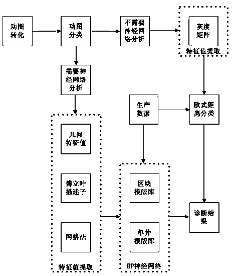
[0103] Embodiment 2: as attached figure 1 , 2 , 3, 4, 5, 6, and 7, a fault diagnosis method of the above-mentioned oil well fault intelligent analysis and decision-making system comprises the following steps:
[0104] The first step is the conversion of the dynamometer diagram. The data acquisition module will transmit the acquired equipment parameters to the operation monitoring module. After updating the expert database, the fault diagnosis system unit will convert the dynamometer diagram measured on the ground into the dynamometer diagram of the downhole rod pump, and the completion is successful. Graph conversion, the steps are as follows:
[0105] Establish the wave equation, the formula is as follows:
[0106]
[0107] In the formula: u(x,t) is the displacement of the cross section of the sucker rod string at the depth x at time t; x is the depth; t is the time; a is the propagation velocity of the stress on the sucker rod string; c is damping coefficient;
[010...
Embodiment 3
[0143] Embodiment 3: as attached figure 1 , 2 , 8, and 9, a failure prediction method of the above-mentioned oil well failure intelligent analysis and decision-making system, comprising the following steps:
[0144] The first step is to extract the eigenvalues of the recent 5 groups of normal dynamometer diagrams of a single well, and then enter the second step;
[0145] The second step is to compare the eigenvalues of the recent 5 groups of normal dynamometer diagrams of a single well with the normal dynamometer diagrams in the template library, calculate the similarity, and then enter the third step;
[0146] The third step is to establish a dynamic model of the data, that is, the GM(h,n) model. Its differential equation is a continuous function in the time domain, h is the order of the equation, and n is the number of variables. The differential equation is shown in the following formula:
[0147]
[0148] Then the coefficient vector of the differential equation ...
PUM
 Abstract
Description
Claims
Application Information
 - R&D
- Intellectual Property
- Life Sciences
- Materials
- Tech Scout
- Unparalleled Data Quality
- Higher Quality Content
- 60% Fewer Hallucinations
Browse by: Latest US Patents, China's latest patents, Technical Efficacy Thesaurus, Application Domain, Technology Topic, Popular Technical Reports.
© 2025 PatSnap. All rights reserved.Legal|Privacy policy|Modern Slavery Act Transparency Statement|Sitemap|About US| Contact US: help@patsnap.com


