Design method for cutter head of laser full fracture surface rock tunnelling machine

A design method and laser disc technology, which is applied to mining equipment, earthwork drilling, tunnels, etc., to achieve the effects of convenient removal, reduced vibration, and improved service life

Active Publication Date: 2017-05-31
DALIAN UNIV OF TECH
5 Cites 25 Cited by

AI-Extracted Technical Summary

Problems solved by technology

In addition, the removal of rock slag and rock powder melted by laser is also a problem
Therefore, ...

Method used

Cutter disc among the present invention adopts two drive shafts to drive laser disc 1 and spoke disc 2 respectively, after laser disc 1 has rotated a circle, the rock that is positioned at laser direct irradiation area can be melted away, and is not irradiated Due to the conduction of high temperature, the strength of the area has also declined, then turn off the laser emitter 1-1 and stop the rotation of the laser disc 1, start to rotate the spoke disc 2, start the high-pressure water gun 3-4 at the same time and make the cutter disc start to slowly move towards At this time, the high temperature caused by the laser will be cooled to a certain extent due to the arrival of high-pressure water flow, thus reducing the working temperature in the subsequent rock breaking work. In addition, the slag brought by the laser rock breaking is also washed away by the high-pressure water flow. At this time, the cutter head does not have a traditional web, so the slag and broken rock powder can be washed away more easily along the water flow. In addition, due to the impact of high-pressure water jets, the high temperature inside the rock will drop rapidly, causing tensile stress inside the rock, which is conducive to the growth of cracks, increasing the number of cracks inside the rock, and reducing the strength of the target rock. When the cutterhead reaches the target rock surface, use the edge scraper 3-2 on the spoke 3 of the cutterhead to remove the remaining rock on the target rock surface. At this time, the strength of the remaining rock has dropped a lot due to the treatment of laser and high-pressure water flow. Therefore, the vibration amplitude caused by cutting the residual rock with the scraper will be much smaller than that of the traditional ...

Abstract

The invention belongs to the technical field of tunnelling of full fracture surface rock tunnelling machines and provides a design method for a cutter head of a laser full fracture surface rock tunnelling machine. A combination of a laser and a high-pressure water jet is adopted to break rock, the rock breaking mode of the cutter head is not dependent on the rolling effect of a hob and rock, therefore, a center plate on a traditional cutter head is removed, a laser device and a high-pressure water gun are driven by different shafts correspondingly, after the rock is treated by the laser, the rock surface is immediately sprayed through the high-pressure water gun, and then the remaining rock is treated through an edge scraper, so that the purpose of rock breaking is achieved. The cutter head does not make contact with the rock surface for most of the time, so that compared with the traditional cutter head, the vibration amplitude of the cutter head can be greatly reduced; molten slag and rock slag can be effectively removed and the high temperature caused by the laser can be reduced due to the existence of a high-pressure water flow; and the cutter head is not provided with the center plate, so that the water flow entrained waste slag can be conveniently discharged out of a working area.

Application Domain

Tunnels

Technology Topic

Water jetRock breaking +9

Image

  • Design method for cutter head of laser full fracture surface rock tunnelling machine
  • Design method for cutter head of laser full fracture surface rock tunnelling machine
  • Design method for cutter head of laser full fracture surface rock tunnelling machine

Examples

  • Experimental program(1)

Example Embodiment

[0030] The specific embodiments of the present invention will be further described below with reference to the drawings and technical solutions.
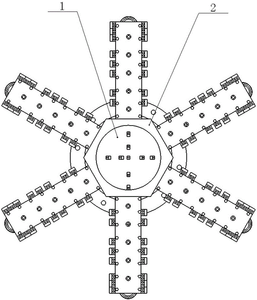
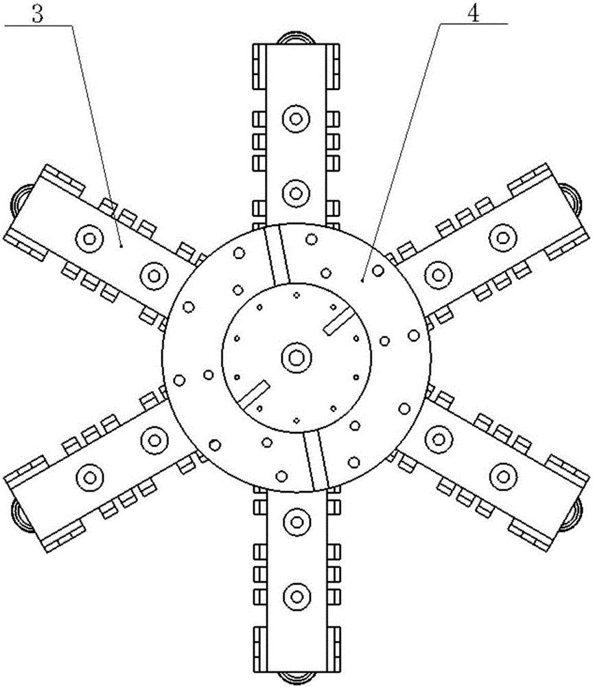
[0031] The traditional full-face rock boring machine uses the overall rotation of the cutter head to make the hob continuously squeeze the rock. When the stress exerted by the hob on the rock is greater than the limit stress of the rock, the rock will crack and break. To achieve the effect of breaking the rock. In this process, the hob is in direct contact with the rock, and the vibration generated by rock breaking will be transmitted to the entire cutter head through the hob. The resulting vibration is huge, which seriously affects the stability and reliability of the roadheader. Sex.
[0032] The invention uses a laser and a high-pressure water gun to break the rock, so that most of the working time of the roadheader is not in direct contact with the rock surface, thus effectively reducing the vibration of the cutter head, improving the stability of the roadheader during work, and improving the worker’s working environment. In terms of structure, the geometric outline of the spoke disk is determined by the number of spokes required during excavation. The angle between the laser generator and the surface of the laser disk can be determined by the actual working conditions. The number of connecting screws between the laser disk 1 and the drive shaft , The number of connecting screws between the spoke plate 2 and the spoke plate holder 4, and the number of connecting screws between the spoke plate holder 4 and the drive shaft can be determined by the on-site working conditions.
[0033] When the laser generator is working, adjust the distance between the cutter head and the target rock surface according to the working conditions of the site and the nature of the rock to determine the laser drilling radius. The laser drilling radius should be smaller than the tunnel radius. This is due to the laser The generated high temperature will weaken the rock, cause cracks to develop, and dehydrate and vaporize the minerals, thereby increasing the void space. This weakening effect not only acts on the directly irradiated rock, but also due to the high temperature conduction, the rock near the laser beam is also It will deteriorate, and its strength will be significantly reduced. Therefore, in order to improve the safety of working in the tunnel, the radius of the rock directly acted on by the laser should be smaller than the radius of the excavated tunnel. The efficiency of laser drilling can be obtained by the following formula under the eight assumptions of the drilling model:
[0034]
[0035] Where P is the laser power, W; d is the laser spot diameter, mm; v d It is the drilling rate, mm/s; ξ and η are constants that depend on the material characteristics and the laser wavelength, which can be determined experimentally. Therefore, the emission power and spot radius of the laser transmitter 1-1 can be adjusted according to the characteristics of the rock through the formula (2) to achieve the ideal drilling rate.
[0036] The cutter head in the present invention uses two drive shafts to drive the laser disk 1 and the spoke disk 2 respectively. When the laser disk 1 rotates one revolution, the rock located in the area directly irradiated by the laser will be melted away, while the unirradiated area is The intensity of the high temperature conduction also decreases, then turn off the laser transmitter 1-1 and stop the rotation of the laser disk 1, start to rotate the spoke disk 2, and at the same time start the high-pressure water gun 3-4 and make the cutter disk start to move forward slowly. At this time, the high temperature caused by the laser will be cooled to a certain extent due to the arrival of the high-pressure water flow, thereby reducing the working temperature in the subsequent rock breaking work. In addition, the slag caused by the laser rock breaking is also washed away by the high-pressure water flow. At this time, the cutter head does not have a traditional web, so the slag and broken rock powder can be washed away along the water flow more easily. In addition, due to the impact of the high-pressure water jet, the high temperature inside the rock will drop rapidly, causing tensile stress inside the rock, which is conducive to the growth of cracks, increasing the cracks inside the rock, and reducing the strength of the target rock. When the cutter head reaches the target rock surface, the edge scraper 3-2 on the cutter head spoke 3 is used to remove the remaining rock on the target rock surface. At this time, the remaining rock has been processed by laser and high-pressure water flow, and its strength has dropped a lot. Therefore, the vibration amplitude caused by the scraper cutting the residual rock will be much smaller than the traditional full-face rock tunneling machine cutter head.
[0037] The invention adopts the method of combining laser and high-pressure water jet to break the rock, so that most of the roadheader does not actually touch the rock, and effectively reduces the vibration of the roadheader. The dual-axis drive is also different from the traditional single-axis drive, which effectively staggers the rock-breaking time of the laser and the high-pressure water jet. After the laser has processed the rock, the low-temperature high-pressure water jet can be greatly reduced. At the same time, high-pressure water flow can be used to remove slag and rock powder. Because the web is removed, the water flow can be easily discharged from the working area.

PUM

no PUM

Description & Claims & Application Information

We can also present the details of the Description, Claims and Application information to help users get a comprehensive understanding of the technical details of the patent, such as background art, summary of invention, brief description of drawings, description of embodiments, and other original content. On the other hand, users can also determine the specific scope of protection of the technology through the list of claims; as well as understand the changes in the life cycle of the technology with the presentation of the patent timeline. Login to view more.

Similar technology patents

Composite metal tile and its making process

InactiveCN1970961Areduce vibrationSolve the noise
Owner:天津以道新型建材有限公司

Charged particle radiation device and soundproof cover

ActiveUS20130082194A1reduce vibration
Owner:HITACHI HIGH-TECH CORP

Classification and recommendation of technical efficacy words

  • Extended service life
  • reduce vibration

Fracturing manifold quick connecting device

Owner:YANTAI JEREH PETROLEUM EQUIP & TECH

Modified asphalt composition with creeping characteristic and preparation method thereof

InactiveCN102020859Aavoid rapid agingExtended service life
Owner:ZHEJIANG WOPUMAN HIGH NEW MATERIALS

Fracturing manifold quick connecting device

Owner:YANTAI JEREH PETROLEUM EQUIP & TECH

Startup control method of brushless DC motor

InactiveUS20060132075A1reduce vibrationcurrent be restrict
Owner:SAMSUNG ELECTRONICS CO LTD

Integrated quiet Motorized Roller Shade System

InactiveUS20100307701A1reduce vibrationreduce transmission of sound
Owner:PETERSON THOMAS
Why Eureka
Try Eureka