
A funnel-shaped film hole structure for turbine blades

A technology of turbine blades and air film holes, which is applied in the direction of supporting components of blades, machines/engines, mechanical equipment, etc., can solve the problems of difficult processing of special-shaped holes and high cost, and achieve improved air film cooling efficiency, low cost, and centrifugal force weakened effect

Inactive Publication Date: 2018-11-20
NORTHWESTERN POLYTECHNICAL UNIV
View PDF5 Cites 0 Cited by
  • Summary
  • Abstract
  • Description
  • Claims
  • Application Information

AI Technical Summary

Problems solved by technology

[0006] In order to improve the air film cooling efficiency of the cylindrical hole shape, and overcome the problems of difficulty in processing special-shaped holes and high cost in the prior art, the present invention proposes a funnel-shaped air film hole structure for turbine blades

Method used


Image

  • A funnel-shaped film hole structure for turbine blades
  • A funnel-shaped film hole structure for turbine blades
  • A funnel-shaped film hole structure for turbine blades

Examples


Embodiment 1

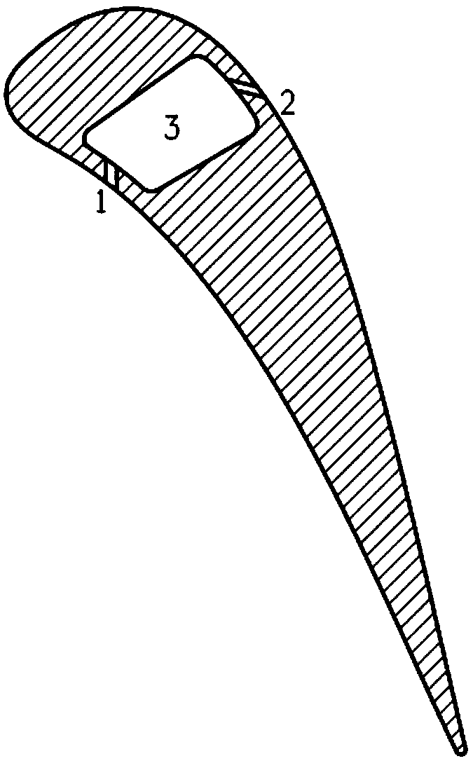
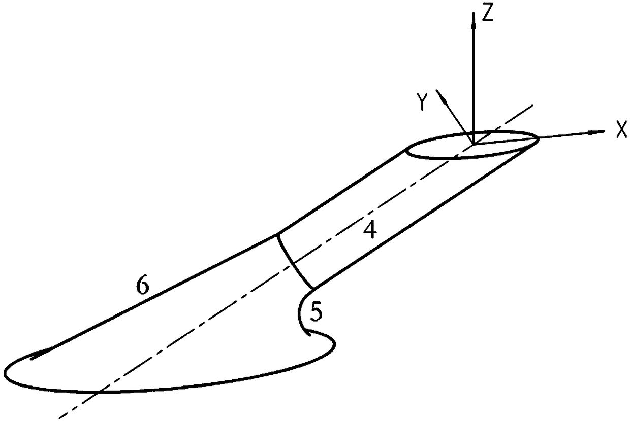
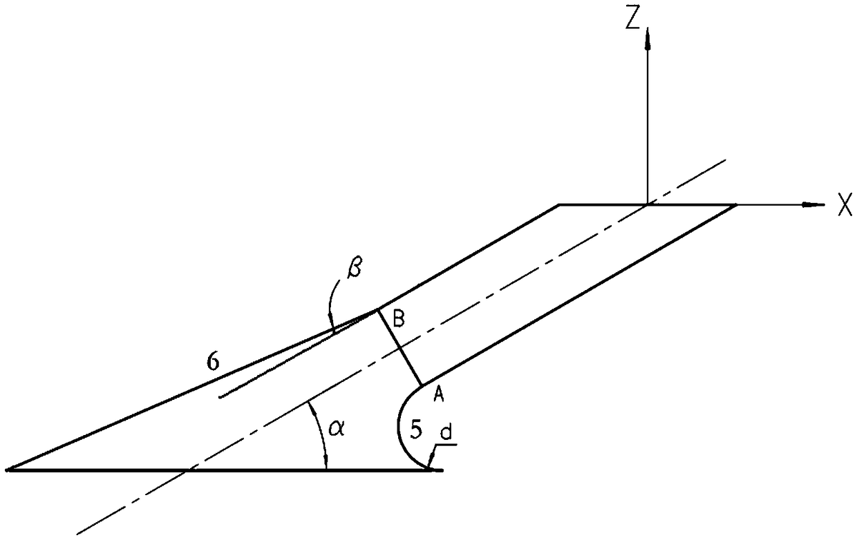
[0024] This embodiment is a funnel-shaped air film hole structure applied to a certain type of turbine blade. The funnel-shaped air film hole 1 on the pressure surface and the funnel-shaped air film hole 2 on the suction surface are respectively arranged on the turbine blade. The two ends of the film hole 1 and the funnel-shaped air film hole 2 on the suction surface respectively form the outlet and the inlet of the airflow, and communicate with the cooling channel 3 in the blade for air supply. The entrance of the inclined cylindrical air film hole 4 is enlarged, the lower wall surface of the inclined cylindrical air film hole inlet is rounded to form an expanded profile, and the upper wall surface of the inclined cylindrical air film hole inlet is expanded into a conical profile surface through conical expansion. The inclination angle α of the inclined cylindrical air film hole 4 is 30°, and the diameter D of the inclined cylindrical air film hole 4 is 2mm. The rounded diame...

Embodiment 2

[0027] This embodiment is a funnel-shaped air film hole structure applied to a certain type of turbine blade. The funnel-shaped air film hole 1 on the pressure surface and the funnel-shaped air film hole 2 on the suction surface are respectively arranged on the turbine blade. The two ends of the film hole 1 and the funnel-shaped air film hole 2 on the suction surface respectively form the outlet and the inlet of the airflow, and communicate with the cooling channel 3 in the blade for air supply. The entrance of the inclined cylindrical air film hole 4 is enlarged, the lower wall surface of the inclined cylindrical air film hole inlet is rounded to form an expanded profile, and the upper wall surface of the inclined cylindrical air film hole inlet is expanded into a conical profile surface through conical expansion. The inclination angle α of the inclined cylindrical air film hole 4 is 45°, and the diameter D of the inclined cylindrical air film hole 4 is 1mm. The diameter of t...

Embodiment 3

[0030]This embodiment is a funnel-shaped air film hole structure applied to a certain type of turbine blade. The funnel-shaped air film hole 1 on the pressure surface and the funnel-shaped air film hole 2 on the suction surface are respectively arranged on the turbine blade. The two ends of the film hole 1 and the funnel-shaped air film hole 2 on the suction surface respectively form the outlet and the inlet of the airflow, and communicate with the cooling channel 3 in the blade for air supply. The inlet of the inclined cylindrical air film hole 4 is enlarged, the lower wall surface of the inclined cylindrical air film hole inlet is rounded to form an expanded profile, and the upper wall surface of the inclined cylindrical air film hole inlet is expanded into a conical shaped surface through conical expansion. The inclination angle α of the inclined cylindrical air film hole 4 is 60°, and the diameter D of the inclined cylindrical air film hole 4 is 0.3 mm. The diameter of the...


PUM


Abstract

The invention discloses a funnel-shaped gas film hole structure for a turbine blade. Three-dimensional profile expanding is performed on the upper wall surface and the lower wall surface of an inlet of a gas film cooling hole; an oblique cylindrical gas film hole is provided with a flow direction tilt angle alpha; a rounding contour line of an expanding part of the lower wall surface of an inlet of a gas film hole and the center point of the lower wall surface of the gas film hole are intersected at a point A; an inclined angle between the expanding part of the upper wall surface of the inlet of the gas film hole and a center line of the oblique cylindrical gas film hole is beta; and an outline line of a cone profile and the center point of the upper wall surface of the gas film hole are intersected at a point B. According to the funnel-shaped gas film hole structure disclosed by the invention, the gas film hole structure is directly processed and formed by rounding once and reaming once, so that the processing technology is simple and the cost is low. According to the funnel-shaped gas film hole structure disclosed by the invention, the fluid steering angle at the lower wall surface of the inlet is greatly reduced, and the fluid is reduced under the effect of centrifugal force, so that the pipe bending effect in the hole is obviously reduced; and the flow vortex intensity of cold gas in the gas film hole is reduced, the flow field is uniform, and after being sprayed from the gas film hole, the cold gas can be better attached and enclosed to the wall surfaces, so that the cooling efficiency of a gas film is obviously improved.

Description

technical field [0001] The invention relates to the cooling technology of the turbine blades of gas turbines, in particular to a funnel-shaped gas film hole structure for the turbine blades. technical background [0002] With the rapid development of gas turbine technology, the inlet temperature of the turbine has far exceeded the temperature limit of the turbine blades, so it is necessary to use advanced cooling technology to cool the turbine blades. Air film cooling is one of the cooling technologies widely used on gas turbine blades. It refers to extracting cooling air from the compressor and transporting it to the internal cooling channel of the turbine blade, flowing out through discrete holes or slots, and under the action of gas Attached near the turbine blades to form a cold air film with a lower temperature to achieve the purpose of isolating the wall from the high-temperature gas and taking away part of the heat radiated from the high-temperature gas or bright flam...

Claims


Application Information

Patent Timeline
Patent Type & Authority Patents(China)
IPC IPC(8): F01D5/18
CPCF01D5/18
Inventor 朱惠人孟通徐杨徐博涵
Owner NORTHWESTERN POLYTECHNICAL UNIV
Learn More