
Waste gas and waste heat reusing system, engine and vehicle

An engine and exhaust gas technology, applied in the field of vehicles, can solve the problems of partial boiling, prolong the warm-up time, increase the loss of cooling liquid heat dissipation, etc., achieve high power and torque output, avoid uneven heating, and compact structure.

Inactive Publication Date: 2017-05-31
NINGBO GEELY ROYAL ENGINE COMPONENTS
View PDF8 Cites 5 Cited by
  • Summary
  • Abstract
  • Description
  • Claims
  • Application Information

AI Technical Summary

Problems solved by technology

[0003] However, the application of low-pressure EGR technology and waste heat recovery technology in supercharged gasoline engines still faces some difficulties
First, the application of low-pressure EGR technology and waste heat recovery technology makes the structural arrangement of the exhaust side of the engine more complicated, which is not conducive to the compact design of the engine
Second, when the engine starts cold at low temperature, the EGR system does not work, the EGR valve is closed, and the coolant flows through the EGR cooler, which increases the cooling loss of the coolant to a certain extent, prolongs the warm-up time, and is not good for the engine's fuel consumption and emissions
Third, in the current application process of waste heat recovery technology, there is a risk of uneven heating of the heat exchanger and local boiling

Method used


Image

  • Waste gas and waste heat reusing system, engine and vehicle
  • Waste gas and waste heat reusing system, engine and vehicle
  • Waste gas and waste heat reusing system, engine and vehicle

Examples


Embodiment Construction

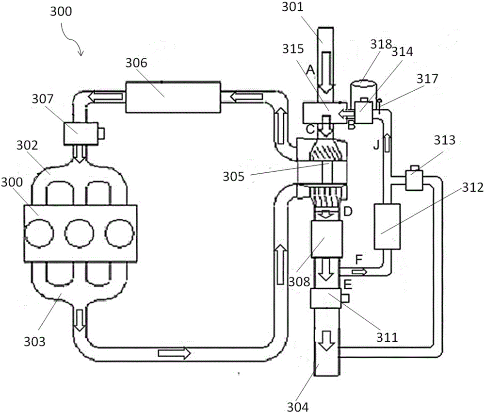
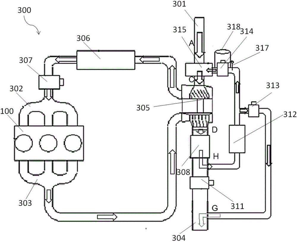
[0042] figure 1and figure 2 It is a structural schematic diagram of an exhaust gas and waste heat recycling system according to an embodiment of the present invention.

[0043] figure 1 or figure 2 The exhaust gas and waste heat recycling system is shown in . The exhaust gas and waste heat recycling system is applied to the vehicle 400 (such as Figure 5 As shown), the vehicle 400 includes an engine 100, an engine water circuit 200 and an engine gas circuit 300, and the exhaust gas and waste heat recycling system includes an EGR system 310 and a waste heat recovery system. The EGR system 310 is arranged at the engine air passage 300 , and is used for cooling the exhaust gas discharged from the engine 100 and then recirculating it back to the engine 100 for reuse, and at the same time using the exhaust gas for warming up the engine 100 . The waste heat recovery system is arranged at the engine waterway 200 , and is used to absorb waste heat through the EGR system 310 to ...


PUM


Abstract

The invention discloses a waste gas and waste heat reusing system, an engine and a vehicle and relates to the vehicles. The waste gas and waste heat reusing system is applied to the vehicle. The vehicle comprises the engine, an engine water path and an engine gas path. The waste gas and waste heat reusing system comprises an EGR system and a waste heat recovery system. The EGR system is arranged at the engine gas path and used for recycling and refluxing waste gas exhausted by the engine into the engine for reusing after the waste gas is cooled and enabling the waste gas to be used for warming up the engine at the same time. The waste heat recovery system is arranged at the engine water path and is used for absorbing waste heat by the EGR system to warm up the engine after low-temperature cold start of the engine. According to the waste gas and waste heat reusing system, the engine and the vehicle, with arrangement of the waste gas and waste heat reusing system on the vehicle engine, the waste heat recovery system is integrated into the EGR system, so that the structure arrangement of the exhaust side of the engine is compacter, and the risks of uneven heating and local boiling of a heat exchanger in the application process of the traditional waste heat recovery technology are prevented.

Description

technical field [0001] The invention relates to a vehicle, in particular to an exhaust gas and waste heat recycling system, an engine and a vehicle. Background technique [0002] EGR (English full name: Exhaust Gas Recirculation, Chinese translation: Exhaust Gas Recirculation) technology and waste heat recovery technology play an important role in engine fuel saving and emission reduction. With the increasingly stringent national emission regulations, the application of EGR technology and waste heat recovery technology will inevitably become the mainstream of engine technology upgrades for major OEMs. [0003] However, the application of low-pressure EGR technology and waste heat recovery technology in supercharged gasoline engines still faces some difficulties. First, the application of low-pressure EGR technology and waste heat recovery technology makes the structural arrangement of the exhaust side of the engine more complicated, which is not conducive to the compact des...

Claims


Application Information

Patent Timeline
Patent Type & Authority Applications(China)
IPC IPC(8): F02M26/06F02G5/02F02N19/10F02D21/08F02D41/00
CPCF02D41/0055F02D41/0077F02D2021/083F02G5/02F02N19/10Y02T10/12
Inventor 旷云龙杨林李连豹蒋恩杰韦虹李双清王瑞平
Owner NINGBO GEELY ROYAL ENGINE COMPONENTS
Learn More