Check patentability & draft patents in minutes with Patsnap Eureka AI!

An electromagnetic brake with buffer structure

A technology of electromagnetic brake and buffer structure, applied in the direction of brake type, axial brake, brake actuator, etc., can solve the problems of brake failure and insufficient safety, so as to prevent failure, improve safety performance and brake effect Good results

Active Publication Date: 2018-12-11
安徽创新电磁离合器有限公司
View PDF7 Cites 0 Cited by
  • Summary
  • Abstract
  • Description
  • Claims
  • Application Information

AI Technical Summary

Problems solved by technology

However, the current electromagnetic brake uses a single brake main spring. Once a fault occurs, it will directly lead to a braking error, which is not safe enough and needs to be improved.

Method used


Image

  • An electromagnetic brake with buffer structure
  • An electromagnetic brake with buffer structure

Examples


Embodiment

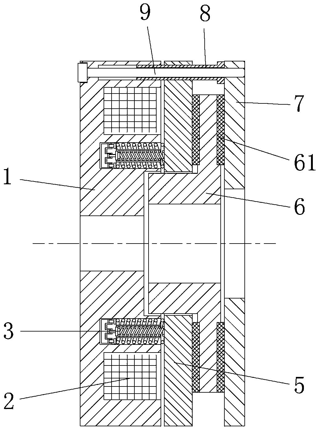
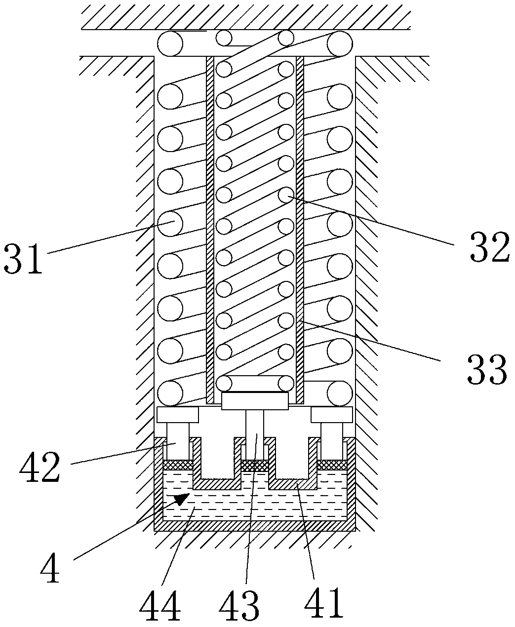
[0017] Example: such as figure 1 and figure 2 As shown, an electromagnetic brake with a buffer structure includes a yoke 1, a coil 2, an armature 5, a brake disc 6, a brake spring 3 and an end cover 7, and the brake disc 6 is arranged between the armature 5 and the Between the end covers 7 , friction plates 61 are provided on the left and right sides of the brake disc 6 , and the two ends of the brake spring 3 abut against the yoke 1 assembly and the armature 5 respectively, Make the armature 5 press the friction plate 61, the yoke 1 is provided with an installation groove, the coil 2 is arranged in the installation groove, and the yoke 1 is provided with a The installation hole of the spring 3, the brake spring 3 includes an outer spring 31, an inner spring 32 and a spacer 33, the spacer 33 is set on the outside of the inner spring 32, and the outer spring 31 is set on the spacer The outer side of the sleeve 33, the spacer sleeve 33 is an aluminum tube sleeve. The inner s...


PUM


Abstract

The invention relates to the technical field of electromagnetic clutches, and particularly to a magnetic brake with buffer structure. The magnetic brake with buffer structure comprises a yoke, a coil, an armature, a brake disk, a brake spring and an end cover. The brake spring comprises an outer spring, an inner spring and a spacer sleeve. The spacer sleeve is sheathed on the inner spring. The outer spring is sheathed on the spacer sleeve. A buffering assembly connected with the end of the brake spring is arranged in a mounting hole. The buffer assembly includes a hydraulic base and a first piston and a second piston arranged on the hydraulic base. The first piston is connected to the end of the outer spring and the second piston is connected to the end of the inner spring. With two springs, the magnetic brake with buffer structure can provide buffer when the armature is attracted, thereby reducing the impact of armature magnetic yoke and reducing the noise during running. At the same time, the elastic potential energy of the inner spring is passed to the outer spring by the piston, which increases the elastic potential energy of the outer spring, thereby improving the braking effect of the spring and improving the safety performance.

Description

technical field [0001] The invention relates to the technical field of electromagnetic clutches, in particular to an electromagnetic brake with a buffer structure. Background technique [0002] Electromagnetic brake is the most commonly used mechanical brake. It controls the clutch of mechanical friction disc through the action of electromagnetic force to realize the braking control of rotating parts. The electromagnetic brake is installed on the shaft or rotating device of the motor to achieve rapid braking or accurate positioning. At present, a common electromagnetic brake includes a fixed rod, an armature, an electromagnet, a brake main spring, an adjustment sleeve and a rear cover, the electromagnet is arranged on one side of the armature, and the rear cover is arranged on the side of the electromagnet On the other side, the fixing rod passes through the through hole on the edge of the back cover and the through hole on the edge of the armature in turn to form a cage fra...

Claims


Application Information

Patent Timeline
Patent Type & Authority Patents(China)
IPC IPC(8): F16D55/14F16D65/14F16D65/54F16D121/20
CPCF16D55/14F16D65/14F16D65/54F16D2121/20
Inventor 朱才文阮社良赵莱福朱筱倩
Owner 安徽创新电磁离合器有限公司
Features
  • R&D
  • Intellectual Property
  • Life Sciences
  • Materials
  • Tech Scout
  • Unparalleled Data Quality
  • Higher Quality Content
  • 60% Fewer Hallucinations
Learn More