Electric cycle oil shock absorber

A technology of circulating oil and shock absorbers, which is applied in the direction of shock absorbers, springs/shock absorbers, shock absorbers, etc., can solve the problems of low response sensitivity and slow return speed, achieve shock absorption capacity guarantee, and improve return Speed, to avoid the effect of too slow return speed

Inactive Publication Date: 2017-05-31
巴南区伟鹏机械加工厂
View PDF0 Cites 1 Cited by
  • Summary
  • Abstract
  • Description
  • Claims
  • Application Information

AI Technical Summary

Problems solved by technology

The disadvantage is that the return speed is slow and the response sensitivity is low.

Method used


Image

  • Electric cycle oil shock absorber

Examples


Embodiment 1

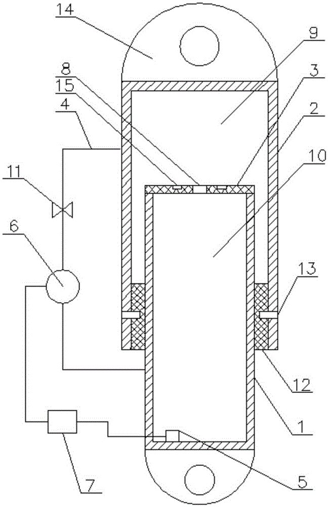
[0033] Such as figure 1 As shown, the electric circulating oil shock absorber includes an inner cylinder 1, an outer cylinder 2, a damping plate 3, a connecting hose 4, a pressure sensor 5, a hydraulic pump 6 and a controller 7; the upper end of the outer cylinder 2 is closed, and the outer The lower end of the cylinder body 2 is open, the upper end of the inner cylinder body 1 is open, and the lower end of the inner cylinder body 1 is closed; the damping plate 3 is arranged on the top of the inner cylinder body 1, and a damping hole 8 is opened on the damping plate 3; the inner cylinder body 1 is slidingly arranged on the outer In the cylinder body 2, the space between the top end of the inner cylinder body 1 and the top end of the outer cylinder body 2 constitutes the oil pressure space 9; the space in the inner cylinder body 1 constitutes the slow pressure space 10; the pressure sensor 5 is arranged in the inner cylinder body 1, The connecting hose 4 communicates with the i...

Embodiment 2

[0039] Such as figure 1 As shown, on the basis of Embodiment 1, the present invention also includes a one-way valve 11 arranged on the connecting hose 4 .

[0040] A one-way valve 11 is provided to prevent the oil from directly entering the pressure-relieving space 10 through the connecting hose 4 during compression of the present invention, so that the shock absorption capacity of the present invention is guaranteed.

Embodiment 3

[0042] Such as figure 1 As shown, this embodiment is based on Embodiment 2, and the check valve 11 is located between the hydraulic pump 6 and the outer cylinder 2 .

[0043] The one-way valve 11 is located between the hydraulic pump 6 and the outer cylinder 2 to prevent oil from entering the hydraulic pump 6 through the connecting hose 4 during compression, thereby protecting the hydraulic pump 6 .


PUM


Abstract

The invention discloses an electric cycle oil shock absorber. The upper end of an outer barrel is closed while the lower end of the outer barrel is opened, and the upper end of an inner barrel is opened while the lower end of the inner barrel is closed; a damp plate is arranged on the top of the inner barrel, and a damp hole and a weak annular groove are formed in the damp plate; the inner barrel is slidably arranged in the outer barrel, and an oil pressure space is formed in a space between the top end of the inner barrel and the top end of the outer barrel; a pressure releasing space is formed in a space in the inner barrel; a pressure sensor is arranged in the inner barrel, a connecting hose communicates with the inner barrel and the outer barrel, and a hydraulic pump is arranged on the connecting hose; the pressure sensor is connected to a controller and the controller is connected to the hydraulic pump. According to the electric cycle oil shock absorber disclosed by the invention, an oil liquid can be directly conveyed to the oil pressure space through the hydraulic pump, so that the problem that the returning speed of the oil liquid is too slow and the oil liquid is unresponsive as the oil liquid in the pressure releasing space passes through the damp hole during returning, and therefore, the returning speed is greatly increased.

Description

technical field [0001] The invention relates to a shock absorbing device. Background technique [0002] Shock absorbers are mainly used to absorb shocks from the road. When passing through uneven roads, filter the vibration of the road surface. Shock absorbers are widely used in automobile suspension systems, rail vehicle suspension systems and aircraft landing gear systems. The main function of the shock absorber is to filter the vibration of the road surface, but its more important role is to improve the comfort of passengers, reduce the impact on the chassis of the car, the frame of the rail vehicle and the fuselage of the aircraft, and the impact on the automobile, rail vehicle and aircraft. security plays an extremely critical role. [0003] The existing shock absorber adopts an oil-air hybrid structure, which uses the damping energy generated when the oil passes through the damping hole, and then uses the compression of the gas to further absorb energy. Its disadva...

Claims


Application Information

Patent Timeline
IPC IPC(8): F16F9/10F16F9/36F16F9/32
CPCF16F9/10F16F9/3207F16F9/3235F16F9/36F16F2222/12
Inventor 余一祥
Owner 巴南区伟鹏机械加工厂
Why Eureka
Try Eureka