Hydraulic continuously variable transmission

A continuously variable transmission and hydraulic technology, applied to components with teeth, belts/chains/gears, mechanical equipment, etc., can solve the problem that the power output of the power output end cannot be manually controlled, the differential ratio cannot be adjusted, and it is not easy to maintain, etc. problems, to achieve the effect of simple structure, improved riding comfort and light operation

Inactive Publication Date: 2017-05-31
王军辉
View PDF11 Cites 1 Cited by
  • Summary
  • Abstract
  • Description
  • Claims
  • Application Information

AI Technical Summary

Problems solved by technology

[0004] At present, the application of hydraulic continuously variable transmission in the automotive field has been very popular. The existing hydraulic continuously variable transmission can only increase the speed of the power output end with the increase of the power throttle or the increase of the speed of the power input end in order to realize the speed change function, that is, The power output ends are all directly controlled by the power input end, and the power output of the power output end cannot be manually controlled, which is embodied in the speed of the power output end. Moreover, the existing continuously variable transmission has many and complicated parts, high cost, and large volume. The torque is small, it is not easy to maintain, and the differential ratio cannot be adjusted. The invention provides a hydraulic continuously variable transmission, which can adjust the differential ratio through the cooperation of hydraulic transmission and speed-adjusting speed-measuring device, and further control the valve through the servo motor. The degree of opening and closing achieves the effect of maintaining the stable speed of the power output end through the speed regulating speed measuring device when the speed of the power input end changes, which is an innovation in the field of continuously variable transmissions

Method used


Image

  • Hydraulic continuously variable transmission
  • Hydraulic continuously variable transmission

Examples


Embodiment

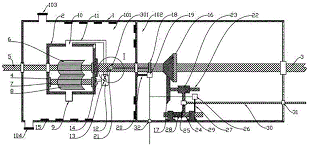
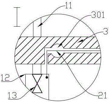
[0029] Embodiment: To further explain the working principle and working process of the present invention, first, a brief introduction is made to the gear pump. The basic form of the gear pump is that two gears with the same size are meshed and rotated in a closely matched housing. The diameter and both sides are closely matched with the shell. The material from the extruder enters the middle of the two gears at the suction port, and fills the space, moves along the casing with the rotation of the teeth, and finally is discharged when the two teeth mesh. A gear pump is also called a positive displacement device, that is, like a piston in a cylinder, when one tooth enters the fluid space of another tooth, the liquid is mechanically squeezed out, because the liquid is not easily compressed, so the liquid The teeth and teeth cannot occupy the same space at the same time, so that the liquid will be discharged. Due to the continuous meshing of the teeth, this phenomenon occurs conti...


PUM


Abstract

Disclosed is a hydraulic continuously variable transmission. The hydraulic continuously variable transmission comprises a box body. A space encircled by the box body comprises a hydraulic oil tank and a speed measurement tank. A gear pump is arranged inside the hydraulic oil tank. A pump body of the gear pump is fixedly connected with a gear pump shaft. The gear pump shaft penetrates through the wall of the hydraulic oil tank to enter the speed measurement tank, then is sequentially provided with an electric brush and a primary cone pulley and penetrates out of the speed measurement tank ultimately. A pair of engaged gears connected with each other through a shaft are arranged inside the pump body of the gear pump. An oil outlet of the pump body of the gear pump is connected with a valve driven by a servo motor through a guide pipe. A speed measurement device is fixed to the tank wall of the speed measurement tank. The speed measurement device comprises a secondary cone pulley capable of making contact with the primary cone pulley to measure the speed, and a speed sensor. The speed sensor is connected with the electric brush through a wire and penetrates through a wire channel formed in the gear pump shaft to be connected with the servo motor. By means of the hydraulic continuously variable transmission, when the rotating speed of a power input end is changed, the effect that the rotating speed of a power output end can be kept stable is achieved through the speed governing and speed measurement device, and hence the hydraulic continuously variable transmission is an innovation in the field of continuously variable transmissions.

Description

technical field [0001] The invention relates to the technical field of transmissions, in particular to a hydraulic continuously variable transmission. Background technique [0002] CVT (CONTINUOUSLY VARIABLE TRANSMISSION) technology is continuously variable transmission technology. It uses the transmission belt and the driving and driven wheels with variable working diameters to transmit power. best match. Common continuously variable transmissions include hydromechanical continuously variable transmission and metal belt continuously variable transmission (VDT-CVT). At present, there are more and more models using CVT in the domestic market. [0003] In order to realize stepless speed change, there are three ways of transmission: liquid transmission, electric transmission and mechanical transmission. There are two types of hydraulic transmission: one is the hydraulic type, which is mainly composed of pumps and motors or variable speed transmissions composed of valves and p...

Claims


Application Information

Patent Timeline
Patent Type & Authority Applications(China)
IPC IPC(8): F16H61/30F16H61/32F16H63/40
CPCF16H61/30F16H61/32F16H63/40F16H2306/00
Inventor 王军辉
Owner 王军辉
Why Eureka
Try Eureka