Heat-engine plant boiler air and flue system and start-stop control method thereof

A technology for start-stop control and thermal power plants, applied in combustion methods, combustion air/fuel supply, non-flammable liquid/gas delivery, etc., can solve the problem of increasing workload and labor costs, increasing operating costs, affecting unit operation, etc. problem, to achieve the effect of automatic start and automatic stop

Active Publication Date: 2017-05-31
NORTH CHINA ELECTRICAL POWER RES INST +1
View PDF6 Cites 3 Cited by
  • Summary
  • Abstract
  • Description
  • Claims
  • Application Information

AI Technical Summary

Problems solved by technology

[0002] In the boilers of thermal power plants, it is necessary to ensure sufficient air intake to ensure the combustion efficiency of the boilers. Most of the existing boilers are directly equipped with intake pipes for the boilers to introduce the outside air into the combustion chamber. However, due to the temperature of the outside air and the furnace There is a large temperature difference, and the introduction of outside air regrets lowering the furnace temperature, thereby reducing the combustion efficiency. If a separate air heating device is added, the operating cost will be increased
Moreover, the existing thermal power plants cannot automatically start the boiler air-smoke system when the boiler air-smoke system is fully stopped, and cannot automatically stop the boiler air-smoke system when the boiler air-smoke system is running. When the smoke system startup program runs to a certain step, if the step condition is not met, the startup program cannot continue to run
That is, the operation and stop of the existing boiler air-smoke system requires human intervention, which greatly increases the workload and labor costs, and if the boiler air-smoke system cannot be started or stopped in time, it may affect the normal operation of the unit

Method used


Image

  • Heat-engine plant boiler air and flue system and start-stop control method thereof
  • Heat-engine plant boiler air and flue system and start-stop control method thereof
  • Heat-engine plant boiler air and flue system and start-stop control method thereof

Examples


Embodiment Construction

[0041]The following will clearly and completely describe the technical solutions in the embodiments of the present invention with reference to the accompanying drawings in the embodiments of the present invention. Obviously, the described embodiments are only some, not all, embodiments of the present invention. Based on the embodiments of the present invention, all other embodiments obtained by persons of ordinary skill in the art without making creative efforts belong to the protection scope of the present invention.

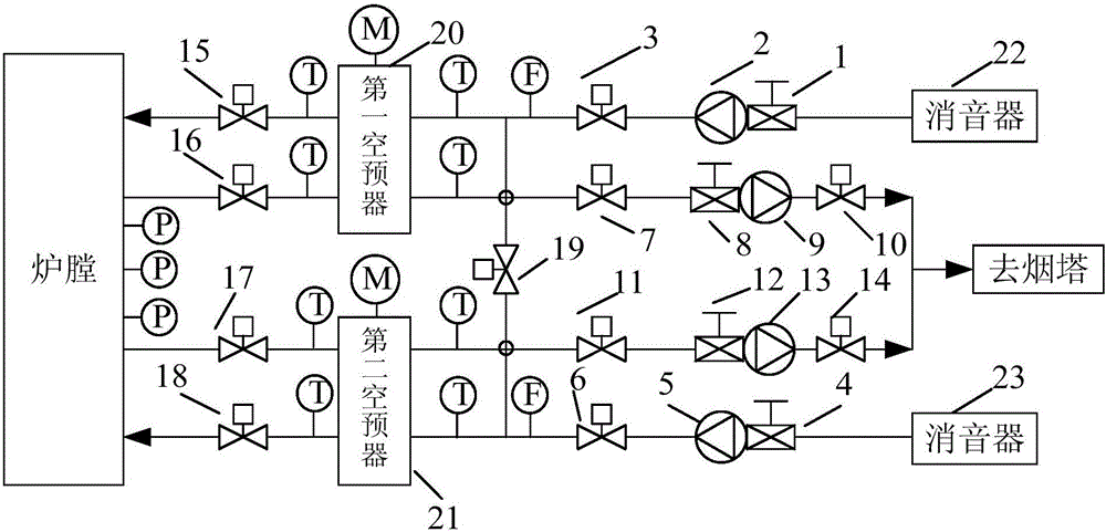
[0042] Such as figure 1 As shown, the embodiment of the present invention provides a thermal power plant boiler air and smoke system, the system mainly includes a first air preheater 20, a second air preheater 21, a first air blower 2, a second air blower 5, a first The induced draft fan 9, the second induced draft fan 13, the outlet main pipe connecting door 19 of the blower fan and a plurality of pipelines.

[0043] The first air blower 2 is connected with t...


PUM


Abstract

The invention provides a heat-engine plant boiler air and flue system and a start-stop control method thereof. The system comprises a first air pre-heater, a second air pre-heater, a first air feeder, a second air feeder, a first induced draft fan, a second induced draft fan, an air feeder outlet mother tube interconnection valve and a plurality of pipes. The air feeders are connected with the air pre-heaters through the pipes, inlets of the air feeders are provided with inlet guide blades, and outlets of the air feeders are provided with outlet electric doors; the air pre-heaters are connected with a boiler hearth through two passages of pipes, one of the pipes is provided with an air pre-heater outlet electric door, and the other pipe is provided with an air pre-heater inlet electric door; the induced draft fans are arranged on the pipes through which the air pre-heaters are connected to a smoke tower, the two ends of the induced draft fans are provided with inlet electric doors and outlet electric doors correspondingly, and inlets of the induced draft fans are furthermore provided with induced draft fans inlet guide blades; and an outlet motor tube of the first induced draft fan communicates with an outlet motor tube of the second induced draft fan through the air feeder outlet mother tube interconnection valve.

Description

technical field [0001] The invention relates to the technical field of thermal power generation, in particular to a boiler air-smoke system in a thermal power plant and a start-stop control method thereof. Background technique [0002] In the boilers of thermal power plants, it is necessary to ensure sufficient air intake to ensure the combustion efficiency of the boilers. Most of the existing boilers are directly equipped with intake pipes for the boilers to introduce the outside air into the combustion chamber. However, due to the temperature of the outside air and the furnace There is a large temperature difference, and the introduction of outside air regrets lowering the furnace temperature, thereby reducing the combustion efficiency. If a separate air heating device is added, the operating cost will be increased. Moreover, the existing thermal power plants cannot automatically start the boiler air-smoke system when the boiler air-smoke system is fully stopped, and canno...

Claims


Application Information

Patent Timeline
Patent Type & Authority Applications(China)
IPC IPC(8): F23L15/00
CPCF23L15/00F23L2900/15043Y02E20/34
Inventor 任彦黄葆华陈晓峰赵宁梅隆庞春凤
Owner NORTH CHINA ELECTRICAL POWER RES INST
Why Eureka
Try Eureka