Shaft hole part positioning method based on cross laser device and machine vision

A cross laser and machine vision technology, applied in the field of automation, can solve problems such as low work efficiency, inability to quickly locate shaft-hole parts, and inability to determine the position of the grasped part and the position and posture of the installed part, etc., to achieve accurate The effect of handling and installation

Inactive Publication Date: 2017-05-31
江苏瑞伯特视觉科技股份有限公司
View PDF5 Cites 17 Cited by
  • Summary
  • Abstract
  • Description
  • Claims
  • Application Information

AI Technical Summary

Problems solved by technology

[0002] In recent years, with the development of modern industry, people aim to improve production efficiency, stabilize and improve product quality, improve workers' working conditions, and accelerate the realization of industrial production mechanization and automation; however, in the prior art, robots are used in handling and installation projects , often because the position and attitude of shaft-hole parts cannot be quickly located, so the position and attitude of the grasped part and the position and attitude of the installed part cannot be determined, which makes the robot unable to adjust the fixture and plan the path in real time, resulting in the robot being unable to accurately carry and installation, work efficiency is low

Method used


Image

  • Shaft hole part positioning method based on cross laser device and machine vision
  • Shaft hole part positioning method based on cross laser device and machine vision

Examples


Embodiment Construction

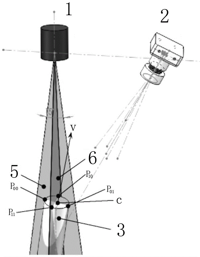
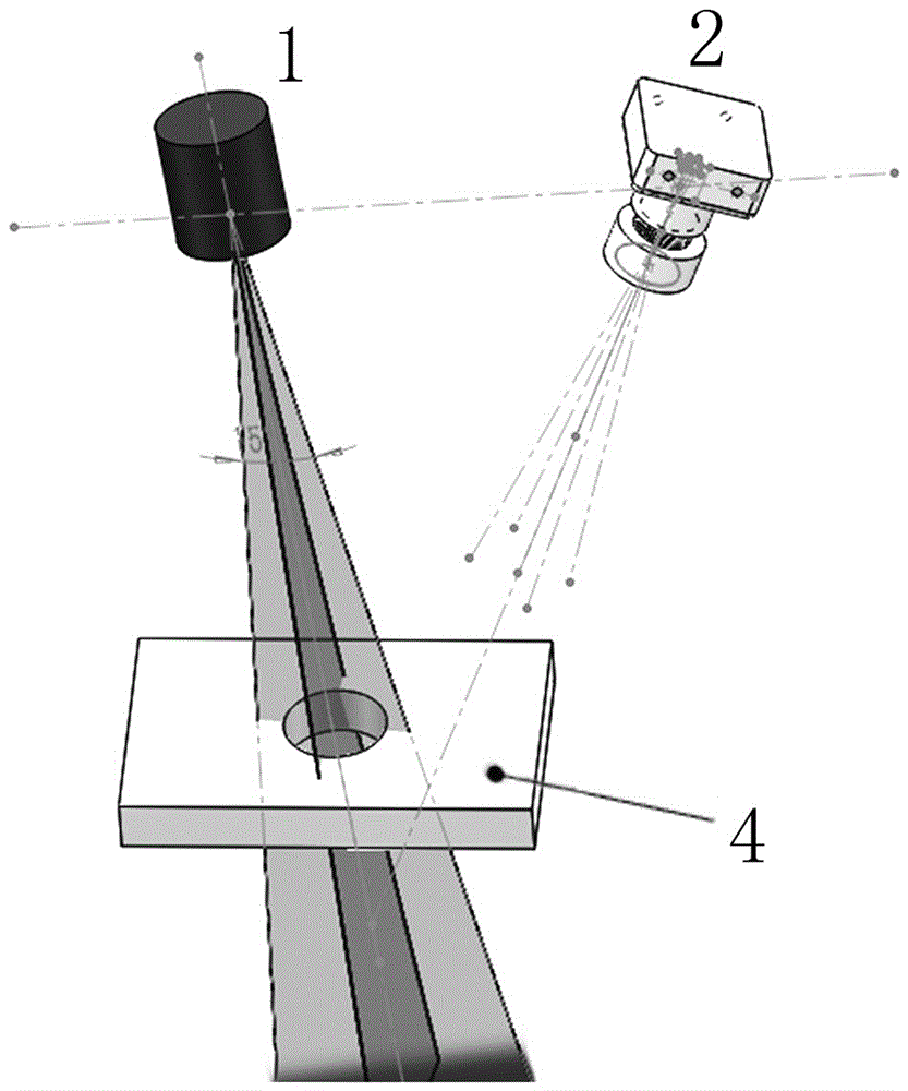
[0063] Such as Figure 1-2As shown, a positioning method for shaft-hole parts based on cross laser and machine vision includes laser 1, camera 2, and shaft-hole parts; laser 1 emits cross lasers to form two intersecting laser light planes to irradiate the shaft End faces of hole parts;

[0064] Shaft and hole parts are divided into shaft parts 3 and hole parts 4. The end face of shaft and hole parts is a space circle, the center is C, and the direction vector is V; the two intersecting laser light planes respectively include the first light plane 5. The second optical plane 6 and the first optical plane 5 cut the end face to form two characteristic breakpoints and , the second optical plane 6 cuts the end face to form two characteristic breakpoints and , are imaged by camera 2 respectively;

[0065] The positioning and attitude determination method specifically includes the following detection steps:

[0066] a) Contour feature point detection: use crosshair structur...


PUM


Abstract

The invention discloses a shaft hole part positioning method based on a cross laser device and machine vision in the automatic field. The method comprises steps that a), contour characteristic point detection, cross structured light is employed, and four points of a space circle are acquired for one time; b), detection on a part end surface normal vector, the normal vector of the space circle is calculated according to the four points; c), detection on a circle center and a radius of the space circle, a partial coordinate system of the space circle is established according to the normal vector, dimension reduction processing on the profile of the space circle is carried out in the partial coordinate system, a non-linear recursion algorithm is further employed, and the circle center and the radius of the space circle in the partial coordinate system are acquired; and d), detection on position and attitude under a robot coordinate system, the normal vector and the position of the circle center of the space circle are transferred to the robot coordinate system, and the position, the attitude and the radius of the space circle under the robot coordinate system are acquired. The method is advantaged in that real-time clamp adjustment and path planning are convenient for a robot, and quick and accurate moving and mounting can be realized.

Description

technical field [0001] The invention relates to the field of automation, in particular to a method for determining the attitude and positioning of shaft and hole parts based on cross laser and machine vision. Background technique [0002] In recent years, with the development of modern industry, people aim to improve production efficiency, stabilize and improve product quality, improve workers' working conditions, and accelerate the realization of industrial production mechanization and automation; however, in the prior art, robots are used in handling and installation projects , often because the position and attitude of shaft-hole parts cannot be quickly located, so the position and attitude of the grasped part and the position and attitude of the installed part cannot be determined, which makes the robot unable to adjust the fixture and plan the path in real time, resulting in the robot being unable to accurately carry And installation, work efficiency is low. Contents ...

Claims


Application Information

Patent Timeline
Patent Type & Authority Applications(China)
IPC IPC(8): G01B11/00G01B11/08
CPCG01B11/002G01B11/08
Inventor 刘凯李龙王志祥
Owner 江苏瑞伯特视觉科技股份有限公司
Why Eureka
Try Eureka