Voltage Dividers for High Voltage Energy Metering Devices

A metering device, high-voltage electric energy technology, applied in the direction of the voltage divider, etc., can solve the problems that the high-voltage voltage divider cannot adjust the measurement accuracy of the heat source, the influence of the linear distribution of the electric field of the two plates, and the difference in the precision of the voltage divider. Uniformity, ensuring linear distribution, and improving the effect of measurement accuracy

Active Publication Date: 2019-05-14
ZHANGJIAKOU POWER SUPPLY COMPANY OF STATE GRID JINBEI ELECTRIC POWER COMPANY +1
View PDF5 Cites 0 Cited by
  • Summary
  • Abstract
  • Description
  • Claims
  • Application Information

AI Technical Summary

Problems solved by technology

[0002] Resistive high-voltage dividers are often used in high-voltage electric energy metering devices to measure AC high voltage. The defect is that due to the existence of high-voltage electric fields, there are distributed capacitances between the high-voltage arm resistors and the shielding body and between various parts of themselves. These capacitances are formed by Spatial stray capacitance is used instead to represent
[0004] However, the internal design and layout of different high-voltage electric energy metering devices are not the same. At the same time, the insulating medium filled between the two electrode plates is usually more sensitive to temperature. The linear distribution of the electric field between the plates will also have a different effect, which in turn will have a different effect on the accuracy of the voltage divider
The high-voltage divider in the above patent cannot be adjusted according to the position of the heat source to avoid the influence of the heat source on the measurement accuracy

Method used


Image

  • Voltage Dividers for High Voltage Energy Metering Devices

Examples


Embodiment

[0030] Embodiment Voltage divider for high-voltage electric energy metering device

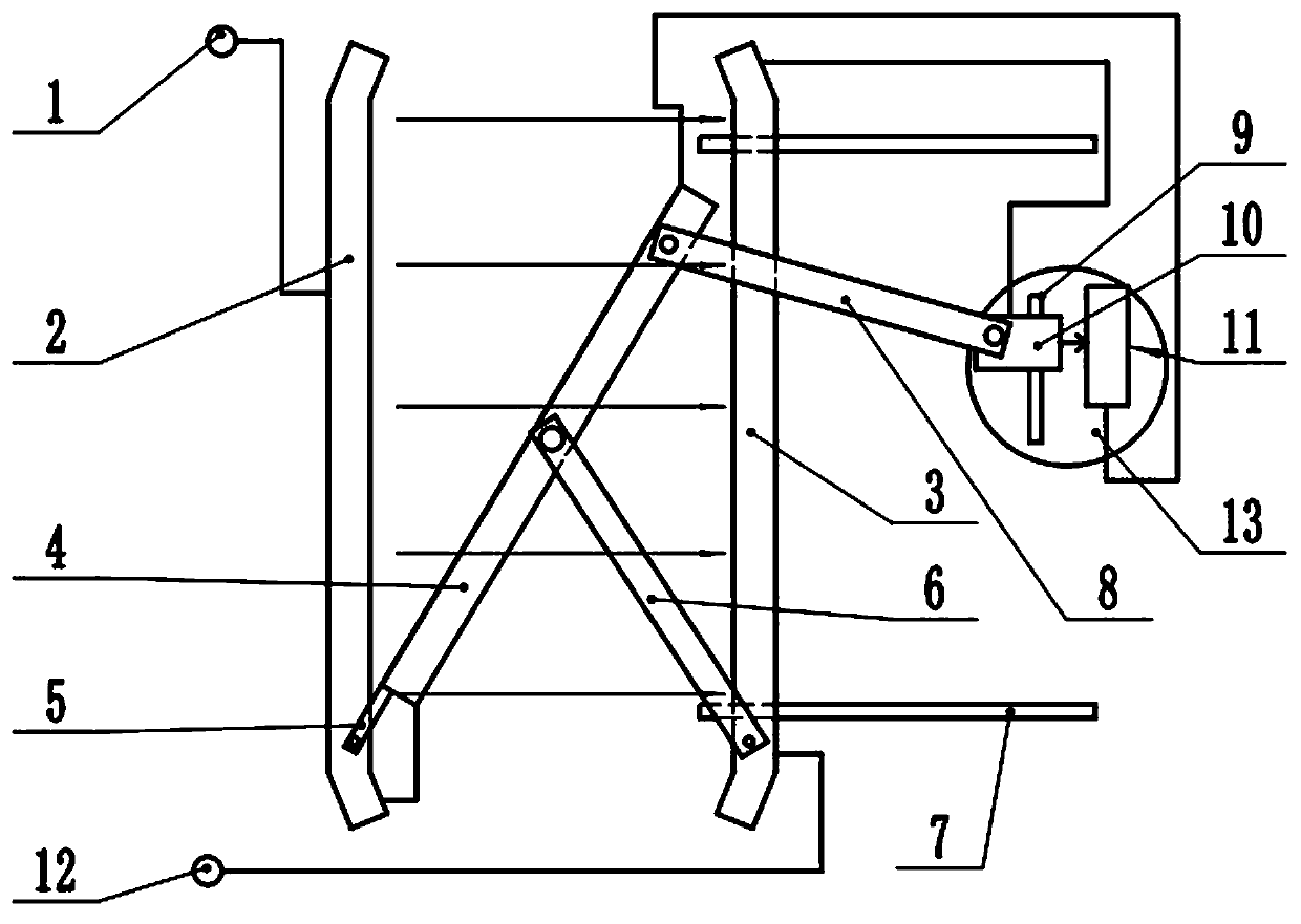
[0031] like figure 1 As shown, this embodiment includes a first connecting terminal 1, a left pole plate 2, a right pole plate 3, a high-voltage arm resistor 4, a low-voltage arm resistor 11 and a second connecting terminal 12, and also includes a horizontal slide rail 7, a rotating bracket 5 and The strut 6 also includes a connecting rod 8 made of insulating material.

[0032] The left pole plate 2 and the right pole plate 3 are set relatively parallel, the high-voltage arm resistor 4 is plate-shaped, placed obliquely between the left pole plate 2 and the right pole plate 3, and the lower end is close to the left pole plate 2, and the upper end is close to the right pole plate 3, The lower end of the high-voltage arm resistor 4 is connected to the left pole plate 2 through a lead wire, the low-voltage arm resistor 11 includes a first pin and a second pin, the first pin is connected to the up...


PUM


Abstract

The invention discloses a voltage divider applied to a high voltage energy metering device. The voltage divider comprises a left polar plate (2), a right polar plate (3), a high voltage arm resistor (4), a low voltage arm resistor (11), a horizontal slide rail (7), a rotating bracket (5) and a strut (6). According to the invention, the distance between the left polar plate (2) and the right polar plate (3) can be adjusted; the rotating bracket (5) and the strut (6) form an isosceles triangular mechanism to ensure that lower and upper ends of the high voltage arm resistor (4) are always close to the left polar plate (2) and the right polar plate (3) in the moving process of the right polar plate (3); the gradient of electric field distribution between electrodes is always consistent with the gradient of voltage distribution on the high voltage arm resistor (4); the voltage divider can be adjusted according to the position of other components with large calorific value relative to the voltage divider; the influence of temperature on the linearly uniform distribution of potential is reduced; and the measurement accuracy is improved. The voltage divider provided by the invention can be used as the voltage divider of various high voltage metering devices.

Description

technical field [0001] The invention relates to a voltage divider, which is used in electric power systems and electric and electronic equipment manufacturing departments to measure power-frequency AC high voltage and DC high voltage, in particular to a voltage divider used in high-voltage electric energy metering devices. Background technique [0002] Resistive high-voltage dividers are often used in high-voltage electric energy metering devices to measure AC high voltage. The defect is that due to the existence of high-voltage electric fields, there are distributed capacitances between the high-voltage arm resistors and the shielding body and between various parts of themselves. These capacitances are formed by Spatial stray capacitance is represented instead. Spatial stray capacitance will cause measurement errors. [0003] In order to reduce the error caused by space stray capacitance and improve the measurement accuracy, the patent document with publication number 1021...

Claims


Application Information

Patent Timeline
Patent Type & Authority Patents(China)
IPC IPC(8): G01R15/04
CPCG01R15/04
Inventor 齐火箭徐海宾张新瑞王嘉宏杨红欣陈炜张婧任志丹许丽丽李占国
Owner ZHANGJIAKOU POWER SUPPLY COMPANY OF STATE GRID JINBEI ELECTRIC POWER COMPANY
Why Eureka
Try Eureka