Device for automatically coupling optical communication sub-assemblies and method for eliminating delaying in coupling procedures

An automatic coupling and sub-module technology, applied in the coupling of optical waveguides, light guides, optics, etc., can solve problems affecting product production, many subjective judgment factors, and difficult to control product quality consistency, so as to improve production efficiency and reduce manpower Production costs, the effect of improving monitoring capabilities

Active Publication Date: 2017-05-31
JIANGSU ALLRAY
View PDF5 Cites 2 Cited by
  • Summary
  • Abstract
  • Description
  • Claims
  • Application Information

AI Technical Summary

Problems solved by technology

At present, most of the coupling process of optical communication sub-modules is realized by manual operation. There are too many subjective judgment factors in the whole process, such as the use habits of fixtures, the cooperation of production line production technology, personnel emotions and other factors. It makes it difficult to control the consistency of product quality obtained through coupling, thus affecting downstream product production

Method used


Image

  • Device for automatically coupling optical communication sub-assemblies and method for eliminating delaying in coupling procedures
  • Device for automatically coupling optical communication sub-assemblies and method for eliminating delaying in coupling procedures
  • Device for automatically coupling optical communication sub-assemblies and method for eliminating delaying in coupling procedures

Examples


Embodiment Construction

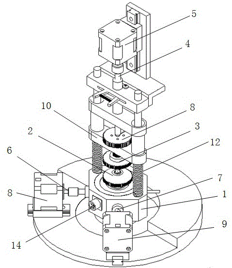
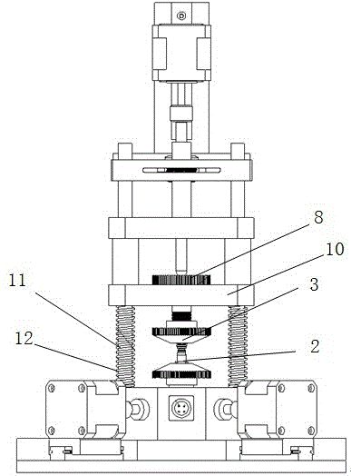
[0031] see Figure 1 to Figure 6 As shown, the optical communication sub-module automatic coupling device includes a base 1, a lower fixture 2 carried on the base 1, an upper fixture 3 arranged corresponding to the lower fixture 2 and located on the lower fixture 2, connected to the upper fixture 3 and vertically Z-axis 4 that moves, Z-axis driver 5 that drives Z-axis 4 to move, X-axis 6 that connects lower fixture 2 and moves laterally, Y-axis 7 that also connects lower fixture 2 and moves laterally, and X-axis that drives X-axis 6 to move The driver 8, the Y-axis driver 9 that drives the Y-axis 7 to move; the lower part of the lower fixture 2 extends into the base 1, the X-axis 6 and the Y-axis 7 are also inserted into the base 1 and connected with the lower fixture 2; the X-axis 6 and the Y-axis The directions of motion of 7 are perpendicular to each other. The optical communication sub-module automatic coupling device also includes a beam 10 and a pair of supporting legs ...


PUM


Abstract

The invention discloses a device for automatically coupling optical communication sub-assemblies and a method for eliminating delaying in coupling procedures. The device comprises a base, a lower fixture, an upper fixture, a Z shaft, a Z shaft driver, an X shaft, a Y shaft, an X shaft driver and a Y shaft driver. The lower fixture is carried on the base, the upper fixture corresponds to the lower fixture and is positioned above the lower fixture, the Z shaft is connected with the upper fixture, can move in the vertical direction and can be driven by the Z shaft driver to move, the X shaft is connected with the lower fixture and can transversely move, the Y shaft is connected with the lower fixture and can transversely move, the X shaft can be driven by the X shaft driver to move, and the Y shaft can be driven by the Y shaft driver to move; the lower portion of the lower fixture extends into the base, and the X shaft and the Y shaft are inserted into the base and are connected with the lower fixture; the movement directions of the X shaft are perpendicular to the movement directions of the Y shaft. The device and the method have the advantages that the traditional multi-operator manual coupling modes can be replaced owing to high-integration modes of equipment, and accordingly the production efficiency can be improved; optical power change can be automatically monitored in real time, accordingly, the product process monitoring capacity can be improved, products with great optical power change can be screened in real time, and the qualification rate of the products can be increased.

Description

technical field [0001] The invention relates to the field of optical communication sub-module manufacturing, in particular to an automatic coupling device for an optical communication sub-module and a method for eliminating hysteresis in the coupling process. Background technique [0002] Optical communication refers to the communication method of transmitting communication data information through optical fiber network, including multiple links from device to system manufacturing. Optical communication has developed rapidly due to its characteristics of wide frequency bandwidth, large capacity, long relay distance, strong anti-interference, and strong confidentiality. Since the 1990s, optical communication has become the main means of transmission of telecommunication services in various countries. The key part of optical communication is a photoelectric conversion process, which converts electricity into light through a semiconductor laser diode, and then transmits inform...

Claims


Application Information

Patent Timeline
Patent Type & Authority Applications(China)
IPC IPC(8): G02B6/42
CPCG02B6/4225
Inventor 宋怀成陈岭
Owner JIANGSU ALLRAY
Why Eureka
Try Eureka