

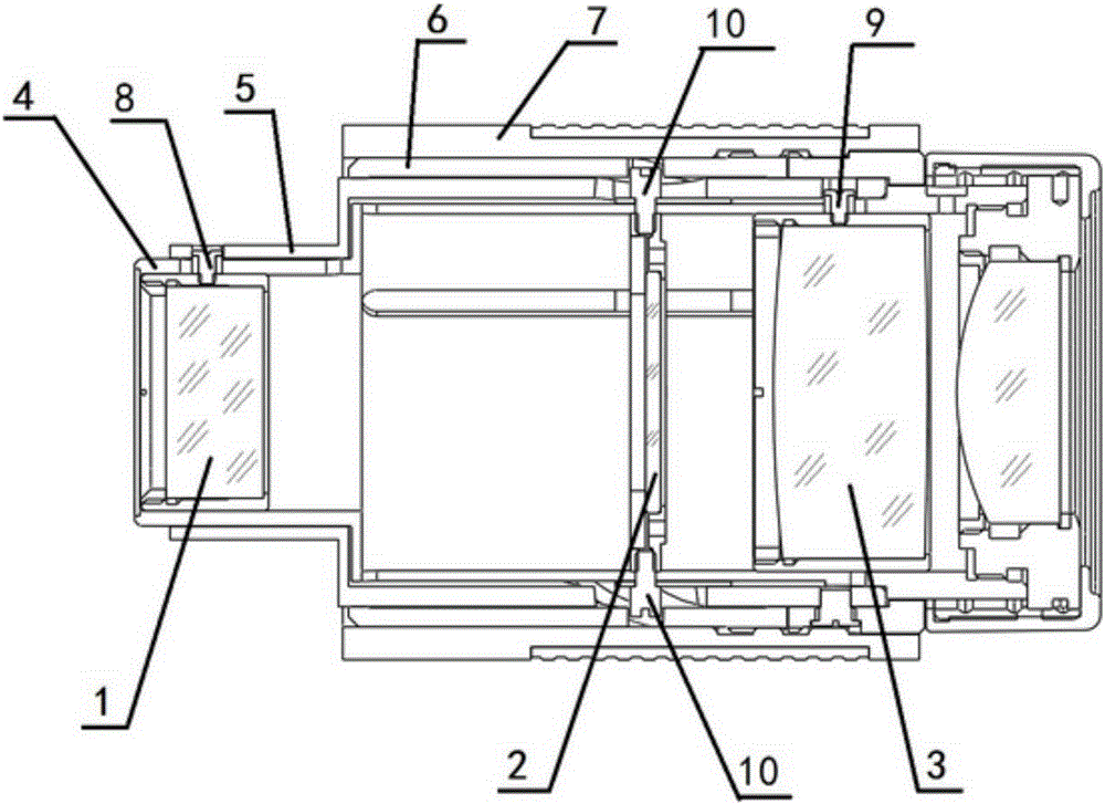
Zoom eyepiece with adjustable reticle
A reticle and adjustable technology, applied in the field of variable magnification eyepieces, can solve problems such as the inability to move the reticle, the inability to place the reticle, and the inability to place the reticle for distance measurement.
- Summary
- Abstract
- Description
- Claims
- Application Information
AI Technical Summary
Problems solved by technology
Method used
Image

Examples
Embodiment Construction
[0037] In describing the present invention, it should be understood that the terms "axial", "upper", "lower", "left", "right", "horizontal", "inner", "outer" and the like indicate directions or The positional relationship is based on the orientation or positional relationship shown in the drawings, which is only for the convenience of describing the present invention and simplifying the description, rather than indicating or implying that the referred device or element must have a specific orientation, be constructed and operated in a specific orientation, Therefore, it should not be construed as limiting the invention. In addition, the terms "first" and "second" are used for descriptive purposes only, and cannot be interpreted as indicating or implying relative importance or implicitly specifying the quantity of indicated technical features. Thus, a feature defined as "first" and "second" may explicitly or implicitly include one or more of these features.
[0038] In the des...
PUM
 Abstract
Description
Claims
Application Information