Display module and adhesion method thereof

A display module and one-sided technology, which is applied in light guides, optics, instruments, etc., can solve the problems of increasing the thickness of the display module, uneven brightness, and increased design size, achieving narrow borders and thin designs, reducing Outer outline size, effect of reducing border width

Active Publication Date: 2017-05-31
WUHAN CHINA STAR OPTOELECTRONICS TECH CO LTD
View PDF10 Cites 7 Cited by
  • Summary
  • Abstract
  • Description
  • Claims
  • Application Information

AI Technical Summary

Problems solved by technology

The advantage of the bottom-mounted backlight is that the light utilization rate is high, and it is easy to realize a large area. The disadvantage is that the brightness is uneven, the thickness is large, and because the outer wheel space of the side-mounted backlight unit is larger than the outline size of the liquid crystal unit, the display module However, as people's demand for portable devices such as notebook computers continues to increase, there is an urgent need for thinner, smaller bezel size, and higher brightness display modules
[0003] figure 1 It is a structural schematic diagram of the opposite side of the backlight light source of the display module in the prior art. The backlight unit includes a plastic frame 22, a reflection sheet 28, a light guide plate 26, and an optical film layer 25. The liquid crystal unit 1 and the backlight unit are bonded together through a bonding glue 21. Together, due to the existence of the plastic frame 22, the outer contour of the backlight unit is much larger than the outer contour of the liquid crystal unit 1, as shown in d1 in the figure, d1 is about 0.2-0.3 mm, which makes the frame of the display module smaller. In addition, since the liquid crystal unit 1 and the backlight unit are bonded together by bonding glue 21, in order to prevent ripples from appearing during display, it is necessary to leave a gap between the lower surface of the liquid crystal unit and the upper surface of the optical film layer 25. A certain gap, as shown in d2 in the figure, d2 is about 0.08mm, which undoubtedly increases the thickness of the display module; again, due to the existence of the plastic frame 22, in order to further realize the narrow frame design, the light guide plate can only be compressed inward edge, the distance d3 between the edge of the light guide plate 26 and the edge of the effective display area of ​​the liquid crystal unit 1 is too small, resulting in the risk of light leakage around the light guide plate, in order to avoid light leakage around the light guide plate, the value of d3 needs to reach 0.5mm , while the value of d3 in the prior art is far less than 0.5mm

Method used


Image

  • Display module and adhesion method thereof
  • Display module and adhesion method thereof
  • Display module and adhesion method thereof

Examples


Embodiment 1

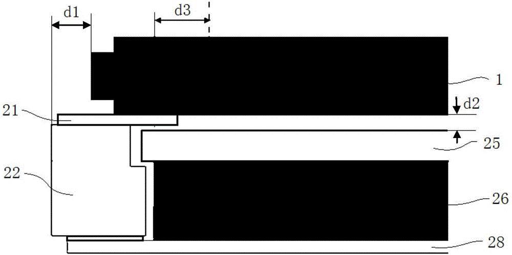
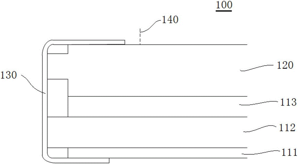
[0031] figure 2 It is a display module 100 of the present invention, which includes a backlight unit and a liquid crystal unit 120 from bottom to top. The backlight unit includes a reflective sheet 111, a light guide plate 112, and an optical film layer 113 in sequence. The liquid crystal unit 120 is arranged on the optical film. Above the layer 113, the backlight unit in this embodiment no longer contains a plastic frame, so the size of the light guide plate 112 can be enlarged, and the projection of the outer contour line of the light guide plate 112 on the liquid crystal unit 120 is the first projection line. The size of 112 can be increased to make the first projected line coincide with the outer contour line of the liquid crystal unit 120, thus increasing the distance between the outer contour line of the light guide plate 112 and the edge 140 of the effective display area of ​​the liquid crystal unit 120, avoiding The risk of light leakage around the light guide plate 1...

Embodiment 2

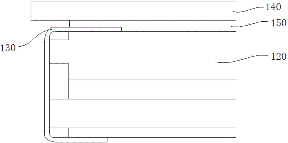
[0035] Figure 4 It is a structural schematic diagram of the display module 200 in this embodiment, which includes a backlight unit and a liquid crystal unit in sequence from bottom to top, the backlight unit includes a reflective sheet 211, a light guide plate 212, and an optical film layer 213 in turn, and the liquid crystal unit includes a first The polarizer 221, the array substrate 222, the color filter 223 and the second polarizer 224, the first polarizer 221 of the liquid crystal unit is attached to the optical film layer 213 of the backlight unit, and the backlight unit in this embodiment no longer contains Plastic frame, so the size of the light guide plate 212 can be enlarged. Preferably, the projection of the outer contour line of the light guide plate 212 on the liquid crystal cell is the first projection line, and the size of the light guide plate 212 can be increased to make the first projection line and The outer contour lines of the liquid crystal unit coincide...


PUM


Abstract

The invention relates to the field of liquid crystal display technology. A display module provided by the invention comprises a backlight unit and a liquid crystal unit, wherein the backlight unit and the liquid crystal unit are arranged in sequence from one side to another side and are integrally combined by using a wrapping adhesive tape; the projection of the peripheral outline of the backlight unit is overlapped with the peripheral outline of the liquid crystal unit. Preferably, the backlight unit and the liquid crystal unit are in seamless adhesion. By adopting the display module, as the size of the outline of the backlight unit is identical to that of the liquid crystal unit, the dimension of an adhesive frame protruding outwards relative to the display unit in the prior art is avoided, so that the size of the outline of the display module is reduced, narrow-frame design of the display module is achieved, meanwhile the distance between the outline edge of the backlight unit and the edge of a display area is increased, and light leakage around the backlight unit is avoided. When the backlight unit and the liquid crystal unit are in seamless adhesion, the thickness of the display module is further reduced, and narrow frame and thinness design of the display module is achieved.

Description

technical field [0001] The invention relates to the technical field of liquid crystal display, in particular to a display module and a bonding method thereof. Background technique [0002] Unlike self-illuminating CRTs and PDPs, liquid crystal displays require an external light source for display because the liquid crystal itself does not emit light. The light source located on the back of the display is called a backlight. According to the positional relationship between the light source (fluorescent lamp, LED, EL, etc.) and the light guide plate, the backlight can be divided into bottom type and side type. The advantage of the bottom-mounted backlight is that the light utilization rate is high, and it is easy to realize a large area. The disadvantage is that the brightness is uneven, the thickness is large, and because the outer wheel space of the side-mounted backlight unit is larger than the outline size of the liquid crystal unit, the display module However, as people'...

Claims


Application Information

Patent Timeline
Patent Type & Authority Applications(China)
IPC IPC(8): G02F1/13357G02F1/1335
CPCG02F1/133514G02F1/133528G02F1/133615G02B6/0021G02B6/0088G02F1/133308G02B6/0055G02F2202/28G02B5/00G02B6/00G02B1/00G02B27/00G02B5/30G02B6/0011G02F1/133524G02B6/0023G02F1/133325G02F1/133354
Inventor 张珍珍
Owner WUHAN CHINA STAR OPTOELECTRONICS TECH CO LTD
Why Eureka
Try Eureka