
Leakage current optimizing method for low-power-consumption product

A leakage current, low power consumption technology, applied in the field of optimizing the leakage current of low power consumption products, can solve problems such as increased leakage current and silicon loss, and achieve the effect of eliminating leakage current

Active Publication Date: 2017-05-31
SHANGHAI HUALI MICROELECTRONICS CORP
View PDF5 Cites 0 Cited by
  • Summary
  • Abstract
  • Description
  • Claims
  • Application Information

AI Technical Summary

Problems solved by technology

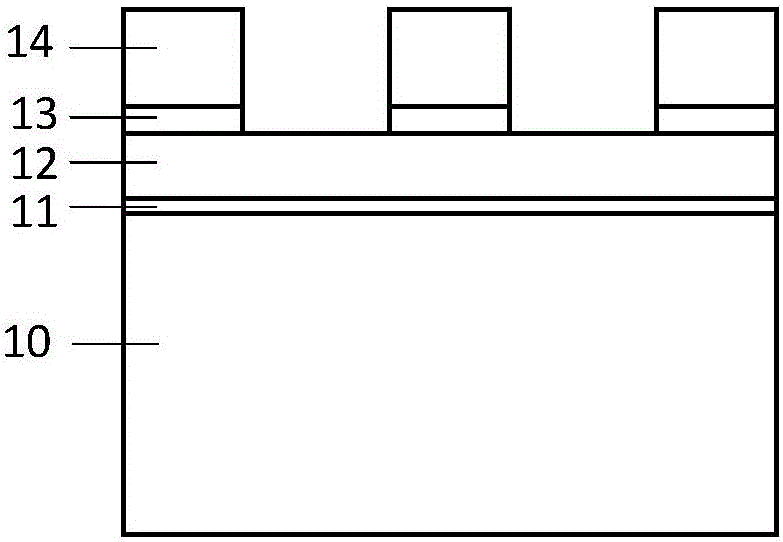
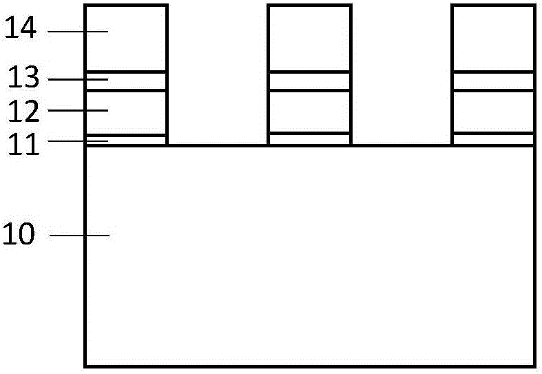
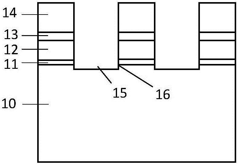
However, when the overetching step removes silicon nitride, it will also cause the top of the silicon substrate to be etched to form a groove 15, resulting in partial silicon loss; and, the conditions commonly used in this step are high bias power, low Polymer gas, which can lead to the formation of pointed topography16 on the top of the silicon substrate groove, and the presence of the sharp topography will lead to a significant increase in leakage current

Method used


Image

  • Leakage current optimizing method for low-power-consumption product
  • Leakage current optimizing method for low-power-consumption product
  • Leakage current optimizing method for low-power-consumption product

Examples


Embodiment Construction

[0035] The specific embodiment of the present invention will be further described in detail below in conjunction with the accompanying drawings.

[0036] It should be noted that, in the following specific embodiments, when describing the embodiments of the present invention in detail, in order to clearly show the structure of the present invention for the convenience of description, the structures in the drawings are not drawn according to the general scale, and are drawn Partial magnification, deformation and simplification are included, therefore, it should be avoided to be interpreted as a limitation of the present invention.

[0037] In the following specific embodiments of the present invention, please refer to figure 1 , Figure 8 It is a flow chart of a method for optimizing the leakage current of low-power products in the present invention; at the same time, please refer to Figure 9-Figure 13 , Figure 9-Figure 13 is realized in a preferred embodiment of the prese...


PUM


Abstract

The invention discloses a leakage current optimizing method for a low-power-consumption product. Photoresist is taken as a template to perform hard mask etching; adhesive removing is performed on a hard mask etching terminal point detection point; then the hard mask is used as a template, a low-bias-voltage-power, high-pressure and high-flow polymer gas is adopted; a smooth morphology on the top of a substrate base material is formed in a process of hard mask over etching, so that an etching switching point changed from the bottom of the hard mask to the top of the substrate base material in a transitional manner in a shallow trench etching process is changed; a sharp corner morphology caused by a conventional way of removing adhesive after hard mask is over-etched, and then etching the substrate base material is eliminated; and therefore, the smooth morphology is formed at the etching starting point on the top of the substrate, so that leakage current caused by a micro sharp corner morphology on the top of the shallow trench can be eliminated fundamentally.

Description

technical field [0001] The invention relates to the field of microelectronics, and more specifically, to a method for optimizing leakage current of low-power consumption products. Background technique [0002] Driven by Moore's Law, the process size of semiconductor devices is gradually shrinking, but the leakage current is gradually increasing, which seriously affects the electrical characteristics and reliability of device circuits. For example, in a CMOS device, as the line width of the gate becomes smaller, the leakage current between the source / drain / gate / silicon substrate of the device will gradually increase. At present, there is still a lack of effective means for reducing the leakage current when a semiconductor device is manufactured using a conventional CMOS process. [0003] see Figure 1-Figure 7 , Figure 1-Figure 7 It is an existing process flow chart for performing shallow trench etching in a hard mask mode. Such as Figure 1-Figure 7 As shown, the existing...

Claims


Application Information

Patent Timeline
Patent Type & Authority Applications(China)
IPC IPC(8): H01L21/308
CPCH01L21/3065H01L21/3081H01L21/3083H01L21/31116H01L21/31144H01L21/67069H01L21/308
Inventor 许进唐在峰陈敏杰任昱吕煜坤
Owner SHANGHAI HUALI MICROELECTRONICS CORP
Learn More