Electric Vehicle Pavement Automatic Charging Tank

An electric vehicle and automatic charging technology, applied in the direction of electric vehicle charging technology, electric vehicles, charging stations, etc., can solve the problems of parking difficulties, waste of time, charging difficulties, etc., to improve haze weather, improve economic benefits, and improve work efficiency. The effect of efficiency and charging effect

Active Publication Date: 2019-06-04
产学研共同体(山东)科技成果转化有限公司
View PDF3 Cites 0 Cited by
  • Summary
  • Abstract
  • Description
  • Claims
  • Application Information

AI Technical Summary

Problems solved by technology

[0003] Nowadays, the charging method of electric vehicles mainly relies on widely installed charging piles. However, charging piles cannot store a large amount of electric energy for electric vehicles in a short period of time. The result is a waste of time and inconvenient
In addition, charging piles can only be installed on expressways or suburban roads, and cannot be installed on bustling urban roads. Electric vehicles run in congested urban areas, parking is difficult, and charging is even more difficult. This is the main obstacle affecting the development of electric vehicles.
[0004] The technology of how to automatically charge an electric vehicle on a running road is being researched in various countries. There is a patent document with the publication number "CN102152746A", which discloses a patent for invention of a "series of road charging and charging devices for electric vehicles", and proposes a The technical solution of wired power supply for electric vehicles while driving on the road has the following disadvantages: the underground electric rail device of the invention is not convenient for automatic connection and receiving electricity, and is not conducive to the popularization and application of automatic charging of electric vehicles while driving on the road

Method used


Image

  • Electric Vehicle Pavement Automatic Charging Tank
  • Electric Vehicle Pavement Automatic Charging Tank
  • Electric Vehicle Pavement Automatic Charging Tank

Examples


Embodiment Construction

[0015] A further description is given below in conjunction with the drawings.

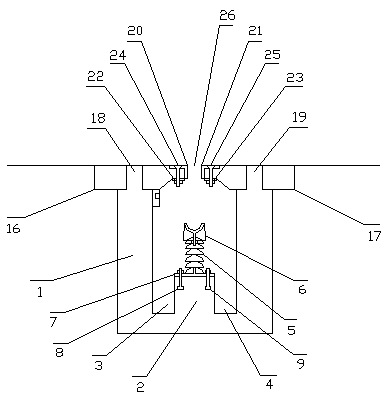
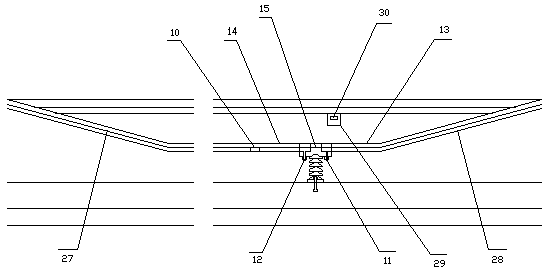
[0016] in figure 1 , figure 2 Wherein, the electric vehicle road automatic charging slot is provided with an underground power supply road section, and the underground power supply road section is set on any section of a highway, a suburban road or an urban road that is directly connected, and the advantage of being set on an urban road is the most prominent. The road sections are usually two-way roads. Each one-way road is divided into a left-turn lane, a straight lane, and a right-turn lane. The underground power supply road sections are all set on the center line of each lane. A long trench is excavated, and a cement tank 1 is set in the long trench. The length of the cement tank is equal to the length of the road section. A water ditch platform 2 is set at the center line of the bottom of the cement tank. The left and right sides of the water ditch platform are drainage ditches 3 and 4 , There ar...


PUM


Abstract

The invention discloses an automatic charging slot of a pavement for an electric vehicle. Underground cement tanks are arranged in middle line pavements of various lanes; a ditch station and a drainage ditch are arranged at the bottom of each cement tank; a plurality of insulating posts are arranged at the upper end of each drainage ditch; an underground electric rail is arranged on each insulating post; all underground electric rails are insulated with one another and are combined with an identification control box to form an independent small power supply unit; the automatic charging slot of the pavement for the electric vehicle is equivalent to a large power supply unit which is formed by combining a plurality underground charging piles; the electric vehicle carries out one charging billing process when passing through each underground electric rail; and when the charging slot is located in the middle of the vehicle, a charging slot tracking indicator light lights on, an automatic electrotome of the electric vehicle can be automatically introduced for charging, and the driving time of the electric vehicle on the pavement is charging time. The crowded motor vehicles on urban roads are like a super large parking lot, precious resources of the urban roads are fully utilized and disadvantages are changed into advantages, so that the work efficiency and the charging effect of the electric vehicle are improved and the economic benefits are improved.

Description

Technical field [0001] The invention relates to a mobile power supply technology of a power supply network power line, to be precise, an automatic road charging tank for electric vehicles. Background technique [0002] At present, the mobile power supply technology of power supply network in our country is still the traditional overhead power line technology, which is mainly used for high-speed rail or trolleybus power supply. The technology of using underground power lines to realize road mobile power supply is still being explored. [0003] Nowadays, the charging method of electric vehicles mainly relies on widely installed charging piles. However, the charging piles cannot store a large amount of electric energy for electric vehicles in a short period of time. The result is a waste of time and inconvenience. In addition, charging piles can only be installed on highways or suburban roads, and cannot be installed on bustling urban roads. Electric vehicles run in congested urban ar...

Claims


Application Information

Patent Timeline
Patent Type & Authority Patents(China)
IPC IPC(8): H02J7/00B60L53/14
CPCB60L53/32H02J7/0027H02J7/0045Y02T10/70Y02T10/7072Y02T90/12Y02T90/14Y02T90/16
Inventor 朱幕松
Owner 产学研共同体(山东)科技成果转化有限公司
Why Eureka
Try Eureka