Charging circuit, charging system, charging method and terminal

A charging circuit and charging method technology, applied in battery circuit devices, secondary battery charging/discharging, circuit devices, etc., can solve the problems of low step-down conversion efficiency and serious heat generation, etc.

Active Publication Date: 2017-05-31
MEIZU TECH CO LTD
View PDF3 Cites 29 Cited by
  • Summary
  • Abstract
  • Description
  • Claims
  • Application Information

AI Technical Summary

Problems solved by technology

[0005] Embodiments of the present invention provide a charging circuit, system, method, and terminal to solve

Method used


Image

  • Charging circuit, charging system, charging method and terminal
  • Charging circuit, charging system, charging method and terminal
  • Charging circuit, charging system, charging method and terminal

Examples


Embodiment 1

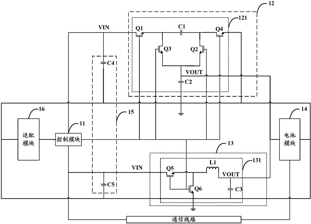
[0028] In order to solve the problems of low step-down conversion efficiency and serious heat generation in existing charging circuits, Embodiment 1 of the present invention provides a charging circuit, which can be applied to terminals such as mobile phones and tablet computers, such as figure 1 As shown, it is a schematic structural diagram of the charging circuit described in Embodiment 1 of the present invention. Specifically, by figure 1 It can be seen that the charging circuit may include a control module 11, a charge pump conversion module 12, a step-down conversion module 13 and a battery module 14, wherein the control module 11 is connected with the charge pump conversion module 12 and the step-down conversion module 12 respectively. The type conversion module 13 is connected; the charge pump conversion module 12 and the step-down conversion module 13 are connected with the battery module 14;

[0029] The control module 11 is configured to collect the voltage and cur...

Embodiment 2

[0106] Embodiment 2 of the present invention provides a charging system, such as Figure 4 As shown in , it is a schematic structural diagram of the charging system described in Embodiment 2 of the present invention. Specifically, by Figure 4 It can be known that the charging system may include an adaptation module 41 and the charging circuit described in the embodiment of the present invention; the adaptation module 41 communicates with the control module 11 in the charging circuit, wherein:

[0107] The control module 11 may be configured to send a first control signal or a second control signal to the charge pump conversion module 12 and the step-down conversion module 13 when determining that the adaptation module 41 is a specific adaptation module ; When determining that the adaptation module 41 is a non-specific adaptation module, send a second control signal to the charge pump conversion module 12 and the buck conversion module 13; the first control signal is used to ...

Embodiment 3

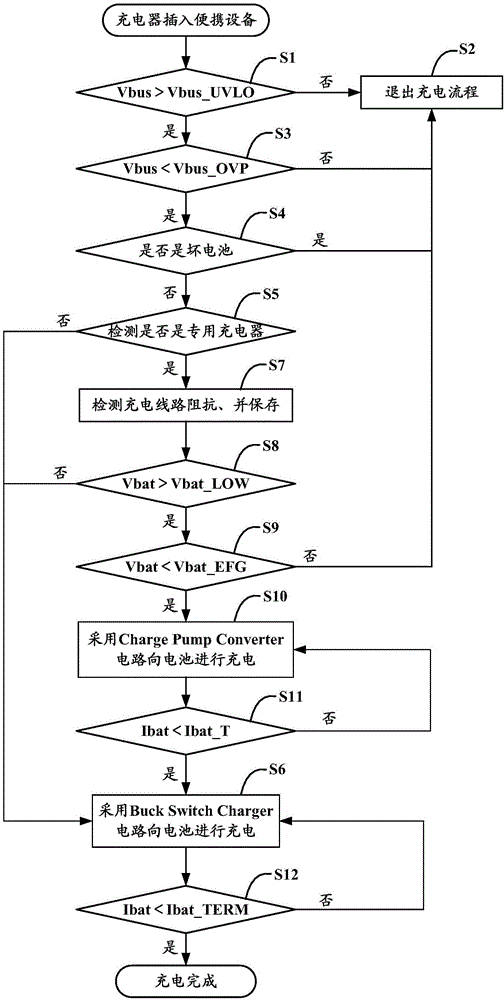
[0118] Embodiment 3 of the present invention provides a charging method, such as Figure 6 , which is a schematic flow chart of the charging method described in Embodiment 3 of the present invention. Specifically, by Figure 6 It can be seen that the charging method may include the following steps:

[0119] Step 601: Detect the voltage and current of the battery module;

[0120] Step 602: Send a control signal to the charge pump conversion module and the step-down conversion module according to the voltage and the current, so as to switch the power-on state of the charge pump conversion module and the step-down conversion module; The control signal includes a first control signal used to control the power-on of the charge pump conversion module and the power-off of the step-down conversion module, and is used to control the power-on of the step-down conversion module and the conversion of the charge pump The second control signal for module power down.

[0121] Further, wh...


PUM


Abstract

The invention discloses a charging circuit, a charging system, a charging method and a terminal. The charging circuit comprises a control module, a charge pump conversion module, a step-down conversion module, and a battery module. The control module is used for collecting the voltage and current of the battery module and sending control signals to the charge pump conversion module and the step-down conversion module according to the voltage and current so as to switch power-on states of the charge pump conversion module and the step-down conversion module. The control signals comprise a first control signal used for controlling the power-on of the charge pump conversion module and the power-off of the step-down conversion module and a second control signal used for controlling the power-on of the step-down conversion module and the power-off of the charge pump conversion module. Since the charge pump conversion module with high efficiency is used, the step-down conversion efficiency is improved, and charging heating is reduced.

Description

technical field [0001] The present invention relates to the technical field of charging, in particular to a charging circuit, system, method and terminal. Background technique [0002] With the continuous improvement of terminal equipment configuration, the demand for power and consumption of terminal equipment become larger and larger, which leads to higher and higher charging frequency of terminal equipment, which seriously affects the charging efficiency of terminal equipment. Reduced user experience. At present, charging circuits based on Buck Switch Charger circuits are often used in the industry to charge terminal devices with high current. [0003] However, since the Buck Switch Charger circuit includes an output inductance with coil loss and magnetic core loss, the buck conversion efficiency of the entire charging circuit may be low (generally speaking, below 91%), making the charging circuit impossible to realize The real high current charging (that is, the chargi...

Claims


Application Information

Patent Timeline
IPC IPC(8): H02J7/04H02J7/10H01M10/44
CPCH01M10/44H02J7/0071H02J7/045H02J2007/10Y02E60/10
Inventor 刘小勇易鹏程
Owner MEIZU TECH CO LTD
Why Eureka
Try Eureka