Low order circulation suppression method for modular multilevel converters

A modular multi-level, circulating current suppression technology, applied in the direction of converting AC power input to DC power output, electrical components, output power conversion devices, etc. , the resonant filter circuit increases the cost, etc., to achieve the effect of high engineering application value, clear physical concept, and simple and convenient realization.

Active Publication Date: 2017-05-31
SOUTHEAST UNIV
View PDF18 Cites 7 Cited by
  • Summary
  • Abstract
  • Description
  • Claims
  • Application Information

AI Technical Summary

Problems solved by technology

However, the design of the resonant filter circuit increases the cost and power consumption; CN104333032A superimposes the double-frequency circulating current component on the basis of the fundamental wave current and the DC component of the converter valve, and the device loss is relatively large; CN104393745A estimates the sub Module voltage, using the modulation method to obtain the number of sub-modules expected to be input in each bridge arm; although it can ensure that the capacitor voltage of the sub-modules in the same bridge arm remains balanced, it does not consider the energy balance between the upper and lower bridge arms
If the uneven distribution of energy occurs between the upper and lower bridge

Method used


Image

  • Low order circulation suppression method for modular multilevel converters
  • Low order circulation suppression method for modular multilevel converters
  • Low order circulation suppression method for modular multilevel converters

Examples


Embodiment Construction

[0035] The present invention will be further described below in conjunction with the accompanying drawings.

[0036] The invention relates to a method for suppressing low-order circulating current of a modular multilevel converter. Its specific implementation method is as follows.

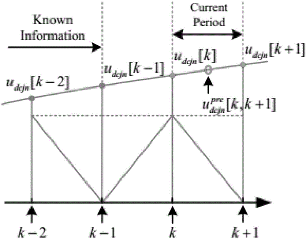
[0037](1) According to the capacitor voltage value u of the upper and lower bridge arm sub-modules of a certain phase collected at the k-1 and k-2 sampling times dcui , u dcli , to obtain the estimated value of the sub-module capacitor voltage for calculation at the kth moment, as follows:

[0038]

[0039] The subscripts j=u, l represent the upper and lower bridge arms respectively, and i=1, 2,..., N, where N represents the number of sub-modules in the bridge arms.

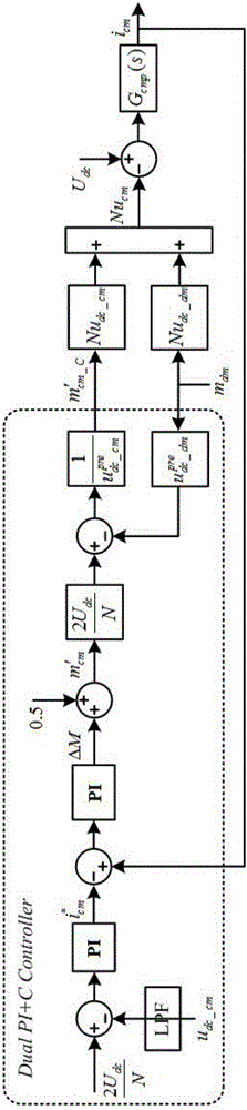
[0040] (2) Calculate the estimated value of the common-mode component and differential-mode component of the capacitor voltage of the phase sub-module and as follows:

[0041]

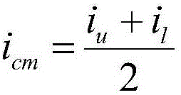
[0042] (3) Collect the current i of the up...


PUM


Abstract

The invention discloses a low order circulation suppression method for modular multilevel converters. The method comprises the steps that according to capacitance voltage values udcui and udcli of a certain phase upper and lower bridge arm module collected in the k-1th and k-2 th sampling time, a sub-module capacitance voltage prediction value for the calculation of the k th time is obtained; estimated values of common and differential modulus components, as shown in the description, of the sub-module capacitance voltage of the phase are calculated, and an actual common mode current icm of the phase is calculated; a reference value of the common modulus current component of the phase, as shown in the description, is calculated, and a common modulus modulation ratio m'cm of the phace with the total DC voltage control capability is calculated; a common modulus modulation ratio of the phase m'cm_C with the low order circulation suppression capability sets the different value between the complimented common modulus modulation ratio m'cm_C and differential modulus modulation ratio mdm as the actual modulation signal of the upper bridge arm of the phase; the sum value between the complimented common modulus modulation ratio m'cm and the differential modulus modulation ratio mdm is set as the actual modulation signal of the lower bridge arm of the phase. The low order circulation suppression method for the modular multilevel converters achieves the suppression of broadband circulation ripple wave, the method is simple and convenient to implement, the physical concept is clear, and the engineering application value is high.

Description

technical field [0001] The invention belongs to the technical field of application of high-voltage and high-power power electronic technology in power systems, and relates to a method for suppressing low-order circulating currents of modular multilevel converters. Background technique [0002] Modular multilevel converter (MMC) is gradually becoming a popular topology for higher power applications due to its special design of cascaded half-bridges that do not require separate half-bridge DC power supplies. They can therefore operate at high voltage levels without losing properties such as modularity, redundancy, and switching frequency harmonic cancellation. Therefore, although MMC was first proposed to be applied to high-voltage direct current transmission systems, it is not suitable for these insulated gate bipolar transistors such as static synchronous compensators (STATCOM), active filters (APF), high-voltage frequency converters, and micro-grid energy storage systems. ...

Claims


Application Information

Patent Timeline
IPC IPC(8): H02M7/483H02M7/5387H02M1/14
CPCH02M1/143H02M7/483H02M7/53871H02M1/0038
Inventor 孙毅超赵剑锋季振东李东野赵亚雄曹武
Owner SOUTHEAST UNIV
Why Eureka
Try Eureka