
Setting method for control loop gain of servo system

A control loop and servo system technology, applied in the field of servo system control, can solve problems such as untargeted processing, achieve the effect of improving positioning effect, simplifying the tuning process, and improving the level of automation and intelligence

Active Publication Date: 2017-05-31
NANJING ESTUN AUTOMATION CO LTD
View PDF6 Cites 5 Cited by
  • Summary
  • Abstract
  • Description
  • Claims
  • Application Information

AI Technical Summary

Problems solved by technology

When running with the parameters of the highest rigidity level, if the system overshoots or shakes, the patent only fine-tunes the integral gain parameters of the speed loop, but does not adjust the gain parameters of the position loop; on the other hand, for the load The end vibration caused by flexibility, the patent has not made targeted treatment

Method used


Image

  • Setting method for control loop gain of servo system
  • Setting method for control loop gain of servo system
  • Setting method for control loop gain of servo system

Examples


Embodiment Construction

[0035] Specific embodiments of the present invention will be described based on the drawings.

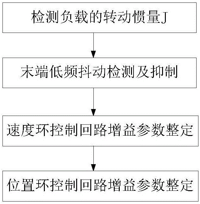
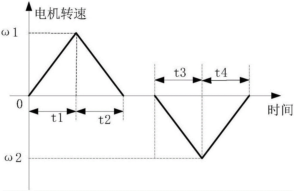
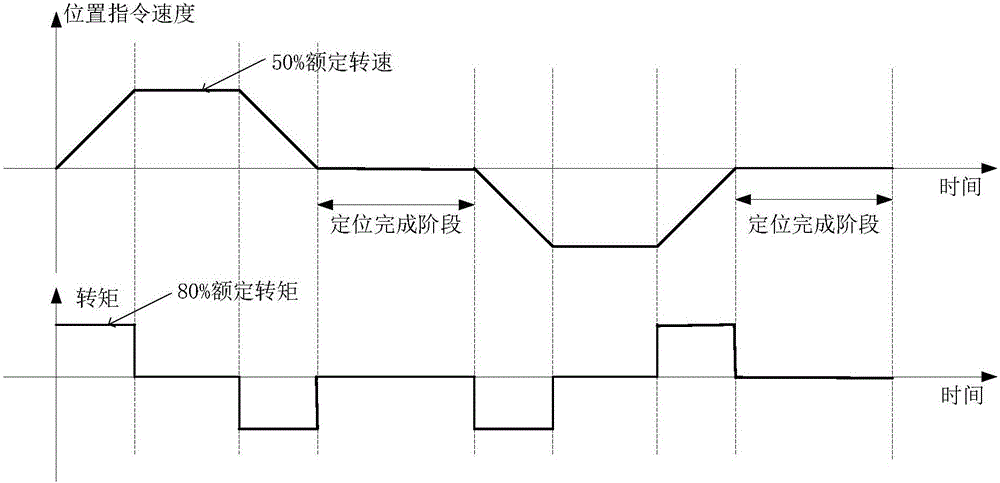
[0036] Such as figure 1 , the tuning method of the present invention mainly includes four steps: 1) detecting the moment of inertia J of the load; 2) detecting and suppressing low-frequency jitter at the end; 3) tuning the gain parameter of the speed loop control loop; 4) tuning the gain parameter of the position loop control loop. The overall implementation principle is as follows Figure 9 As shown, it is divided into the gain parameter tuning of the position loop control loop and the speed loop control loop; before the tuning starts, first determine the simplified load model parameters, that is, the moment of inertia J of the load, which is used to match the parameter Jt in the speed loop control loop , that is, the moment of inertia ratio of the load; in order to obtain a better positioning effect, it is necessary to detect and suppress the low-frequency jitter at the end; then...


PUM


Abstract

The invention discloses a setting method for the control loop gain of a servo system. The setting method is characterized in that the servo system automatically sets gain parameters of servo control loops during reciprocating motion, specifically the gain parameters of a position loop control loop and a speed loop control loop. The method comprises the following steps: before starting of the setting, firstly determining a simplified load model parameter, namely, determining a rotational inertia J of a load; secondly, performing tail-end low-frequency jitter detection and suppression; thirdly, setting the gain parameters of the speed loop control loop; finally, setting the gain parameters of the position loop control loop. By adopting the method, the servo system can automatically set the gain parameters of the servo control loops, including a position loop proportional gain Kp, a speed loop proportional gain Kv, a position loop integral time constant Ti and a torque filter time constant Tf, during the reciprocating motion; moreover, the low-frequency jitter suppression at the tail end of the load and vibration suppression of mechanical resonance are finished, the tuning process of the servo system is simplified effectively, and the automation degree and intelligence level are increased.

Description

technical field [0001] The invention belongs to the technical field of servo system control, and relates to a method for setting the gain of a servo system control loop. Background technique [0002] In practical applications, affected by factors such as the connection mechanism between the servo motor and the load, the moment of inertia of the load, and mechanical resonance, it is necessary to frequently adjust the gain parameters of the servo system control loop to meet the system stability, static and dynamic performance requirements. Since there are many control gain parameters of the servo system, and the parameters are interrelated, this greatly increases the difficulty of on-site application debugging, which is not conducive to the improvement of production efficiency. In this context, studying the tuning technology of servo system gain parameters and implementing corresponding functions in servo products can greatly reduce the technical threshold of servo system appl...

Claims


Application Information

Patent Timeline
Patent Type & Authority Applications(China)
IPC IPC(8): H02P21/00H02P21/18H02P21/05
CPCH02P21/0017H02P21/05
Inventor 杨凯峰李军良齐丹丹
Owner NANJING ESTUN AUTOMATION CO LTD
Learn More