
Device for removing impurities from the lubricating oil of an internal combustion engine

A technology of internal combustion engine and lubricating oil, which is applied in the direction of engine lubrication, pressure lubricant, mechanical equipment, etc., can solve the problems of interference noise and efficiency reduction, and achieve the effect of small material thickness and simplified manufacturing.

Active Publication Date: 2017-05-31
HENGST WALTER
View PDF8 Cites 4 Cited by
  • Summary
  • Abstract
  • Description
  • Claims
  • Application Information

AI Technical Summary

Problems solved by technology

The problem addressed in this document is to avoid disturbing vibrations at the end of the rotor shaft due to the unbalance of the rotor of the centrifuge, which lead to a loss of efficiency and lead to disturbing noise

Method used


Image

  • Device for removing impurities from the lubricating oil of an internal combustion engine
  • Device for removing impurities from the lubricating oil of an internal combustion engine
  • Device for removing impurities from the lubricating oil of an internal combustion engine

Examples


Embodiment Construction

[0025] In the following description of the figures, identical parts are always provided with the same reference numerals, so that for each figure it is not necessary to explain all reference numerals which appear therein anew.

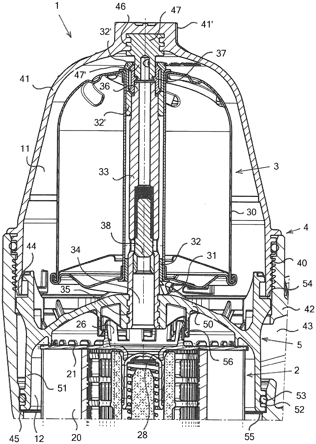
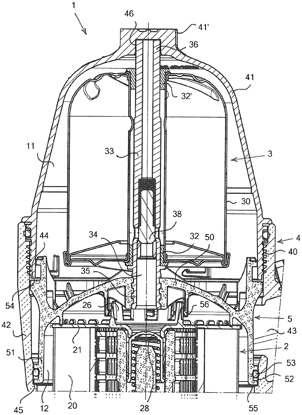
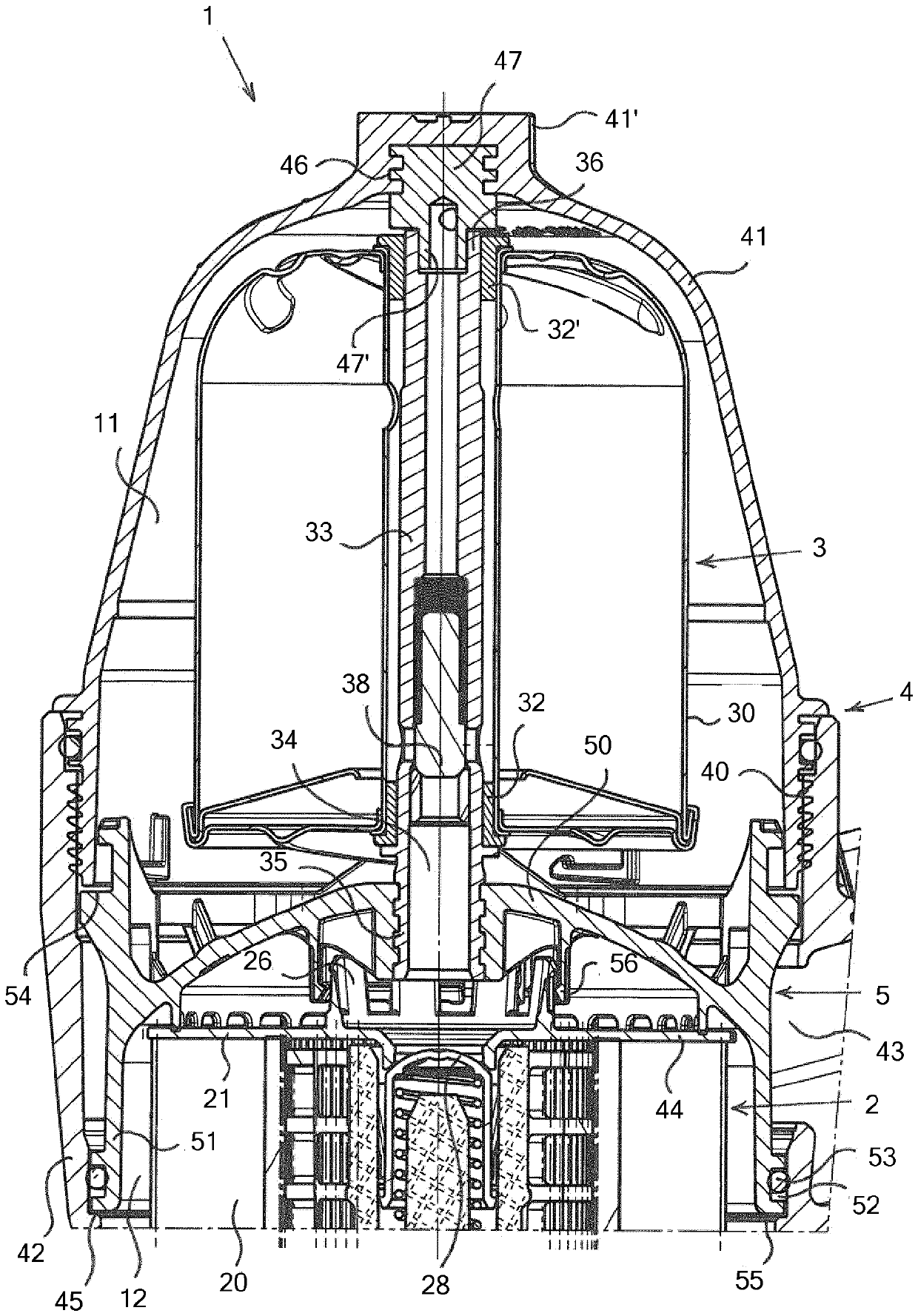
[0026] Attached figure 1 The device 1 for removing impurities from lubricating oil of an internal combustion engine in a first embodiment is shown in longitudinal section.

[0027] The device 1 has a housing 4 which is formed from a fixed lower housing part 42 , only partially shown here, and an upper, arranged cover 41 detachably connected thereto.

[0028] The cover 41 is designed here as a screw cap, which can be screwed and unscrewed by means of a screw thread 40 to a fixed lower housing part 42 . Externally, the cover 41 has at its central upper region a hexagon 41' which is used to place a tightening tool (for example a wrench) when the cover 41 is screwed or unscrewed.

[0029] In the housing 4 one above the other, the filter insert 2 is ...


PUM


Abstract

The invention relates to a device (1) for removing impurities from the lubricating oil of an internal combustion engine, wherein the device (1) has a filter insert (2) at the bottom in the operating position of the device and a centrifuge (3) thereabove having a rotationally drivable rotor (30), wherein the filter insert (2) and the centrifuge (3) are arranged one above the other in a common two-part housing (4), which is closed during the operation of the device (1) and which has a removable upper closure cover (41) and a fixed lower housing part (42), wherein a removable intermediate cover (5) is arranged in the housing (4) between the filter insert (2) and the centrifuge (3), which intermediate cover is inserted in a sealing manner and separates a lower filter space (12), which is under the lubricating oil pressure during the operation of the device (1), from an unpressurized upper centrifuge space (11), wherein the intermediate cover (5) is supported radially outside on the closure cover (41) when the closure cover (41) is in the closed state, wherein a rotor shaft (33) rotatably supporting the rotor (30) is attached in or on the intermediate cover (5) by means of a lower end (35) of the rotor shaft and wherein the rotor (30), the intermediate cover (5) together with the rotor axis (33), and the filter insert (2) can be removed from the housing (4) when the closure cover (41) is in the open state. The device (1) according to the invention is characterized in that the closure cover (41) has a supporting surface at the center of the closure cover on the inside and that the rotor shaft (33) is supported axially on the closure cover (41) at the supporting surface by means of an upper end (36) of the rotor shaft when the closure cover (41) is in the closed state.

Description

technical field [0001] The invention relates to a device for removing impurities from lubricating oil of an internal combustion engine, wherein in its operating state, the device has a filter element at the bottom and a centrifugal separator with a rotatably driven rotor above it. Machines in which the filter cartridge and the centrifuge are arranged one above the other in a common two-part housing part which is closed during operation of the device and has a detachable upper cover and a fixed lower housing part In the housing, in which there is arranged a sealingly inserted removable partition between the filter element and the centrifuge, which will be under lubricating oil pressure during operation of the device The filter chamber is separated from the unpressurized upper centrifuge chamber, wherein, in the case of a closed cover, the partition is supported radially on the outside at the cover, wherein the rotor shaft, which rotatably carries the rotor, is Its lower end is...

Claims


Application Information

Patent Timeline
IPC IPC(8): F01M1/10
CPCF01M1/10F01M2001/1035
Inventor W.阿尔德斯
Owner HENGST WALTER
Learn More