Defect identification method and system

A defect identification and defect technology, applied in the field of image recognition, can solve the problem that the detection method cannot know the specific location of the defect, etc.

Active Publication Date: 2017-06-06
SHENZHEN HUAHAN WEIYE TECH
View PDF5 Cites 28 Cited by
  • Summary
  • Abstract
  • Description
  • Claims
  • Application Information

AI Technical Summary

Problems solved by technology

[0005] The present invention provides a defect identification method and system to solve the technic

Method used


Image

  • Defect identification method and system
  • Defect identification method and system
  • Defect identification method and system

Examples


Embodiment 1

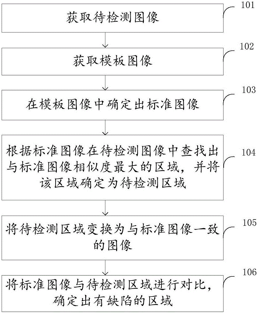
[0036] Please refer to figure 2 , the defect identification method of the defect identification system in this embodiment includes:

[0037] Step 101 , acquiring an image to be inspected. The image to be inspected is an image of a photographed inspection object made on a real object, and the inspection object includes at least one element.

[0038] Specifically, production includes printing, printing, hot pressing, engraving, etching and other processes. Elements can be characters, letters, symbols, words, numbers, strokes, patterns, etc. Each element forms a connected area, and multiple elements can form a A single word, a character string, a sentence or a picture can be used in this way, for example, to represent advertising phrases, logos or trademarks, etc.

[0039] Step 102, acquiring a template image, which is an image including a defect-free detection object.

[0040] The template image can be obtained by taking pictures with a camera or a camera, or can be made by i...

Embodiment 2

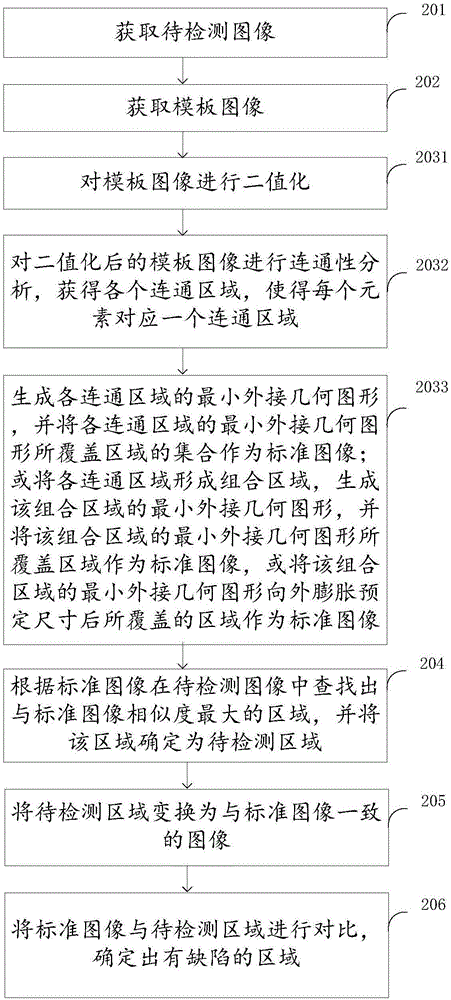
[0119] Please refer to Figure 7 , this embodiment provides a defect identification method, including:

[0120] Step 301 , acquiring an image to be inspected. The image to be inspected is an image of a photographed inspection object made on a real object, and the inspection object includes at least one element.

[0121] Step 302, acquiring a template image, which is an image including a defect-free detection object.

[0122] In step 303, a standard image is determined from the template image. After obtaining the connected regions of each element according to steps 2031 and 2032 in Embodiment 1, obtain the minimum circumscribed geometric figure of each element, such as the minimum circumscribed rectangle, such as Figure 5 The dotted line shown in , and the collection of the area covered by the minimum circumscribed geometry of each element is taken as the standard image. or as Figure 6 As shown, each connected area is formed into a combined area, and the smallest circumsc...

Embodiment 3

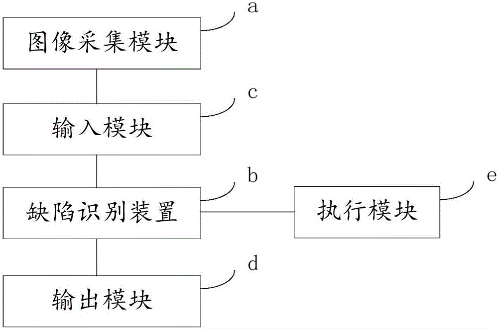
[0132] Please refer to Figure 8 , this embodiment provides a defect identification system, including an image to be inspected acquisition module 401 , a template image acquisition module 402 , a standard image determination module 403 , an area to be inspected determination module 404 , a transformation module 405 and a defect determination module 406 .

[0133] Wherein, the image to be detected acquisition module 401 is configured to obtain an image to be detected. The image to be detected is an image made on a real object of a photographed detection object, and the detection object includes at least one element.

[0134] The template image acquiring module 402 is configured to acquire a template image, where the template image is an image including a defect-free detection object.

[0135] A standard image determination module 403, configured to determine a standard image in the template image, the standard image is the area covered by the minimum circumscribed geometric fig...


PUM


Abstract

The present invention provides a defect identification method and system. The method comprises: obtaining an image to be detected and a template image; determining a standard image in the template image, wherein the standard image is a set of an area covered by the minimum external geometric figure of a detection object, an area covered after the minimum external geometric figure of the detection object expands outwards with a preset size or an area covered by the minimum external geometric figure of each element; searching out an area having the most similarity to the standard image from the image to be detected according to the standard image, and determining the area as an area to be detected; converting the area to be detected as an image consistent to the standard image; and comparing the standard image with the area to be detected, determining the area having defects. The defect identification method can identify whether there are defects in the area to be detected and can obtain the concrete positions of the defects.

Description

technical field [0001] The invention relates to the field of image recognition, in particular to a defect recognition method and system. Background technique [0002] Optical Character Verification (OCV for short) is a machine vision software tool used to check the printing or marking quality of characters or graphics. This technology is mainly used to check the printing quality of characters or patterns, such as contrast, clarity, incompleteness, shear deformation, etc., and finally mark or reject samples with unqualified quality. In OCV vision software, there are high requirements for the processing capabilities of text shearing and rotation errors, image brightness changes, text omissions, and similar characters (such as O and 0, 1 and l, 8 and B, etc.) . [0003] At present, there is an OCV detection method based on regional features, which uses a template to segment the image to obtain the foreground and background features of the template area, then segment the image...

Claims


Application Information

Patent Timeline
IPC IPC(8): G06T7/00G06T7/70
Inventor 杨洋
Owner SHENZHEN HUAHAN WEIYE TECH
Why Eureka
Try Eureka