Ultrasonic cleaning machine for high-speed steel

A technology of ultrasonic cleaning and high-speed steel, which is applied in the direction of cleaning methods using tools, cleaning methods using liquids, cleaning methods and utensils, etc. It can solve the problems of poor cleaning effect, easy damage, and affecting production efficiency, etc. environmental effects

Pending Publication Date: 2017-06-09
江苏伟建工具科技有限公司
0 Cites 1 Cited by

AI-Extracted Technical Summary

Problems solved by technology

[0002] In the fields of food, hygiene, medicine, etc., there are manual traditional cleaning or spray cleaning methods for container cleaning. This method is labor-intensive, and the containers collide with each other and are easily damaged, and the hygienic condition cannot be guaranteed.
In recent years, ultrasonic waves have been used for cleaning. Ultrasonic cleaning uses the cavitation, acceleration, and straight-forward effects of ultrasonic waves in liquids to directly and indirectly affect liquids and dirt, so that the dirt layer is dispersed and emulsified. , stripping to achieve the purpose of cleaning, most of its structure adopts the method of ultrasonic cleaning tank and drying. The ultrasonic cleaning machine is mainly composed of two parts: an ultrasonic cleaning tank and an ultrasonic generator. The ultrasonic transducer vibrator is installed at the bottom; the ultrasonic generator generates high frequency and high voltage, which is transmitted to the transducer through the cable connection line, and th...

Abstract

The invention discloses an ultrasonic cleaning machine for high-speed steel, which is characterized in that the cleaning machine includes a frame; an ultrasonic cleaning liquid storage tank and an ultrasonic generator are arranged in the frame; the upper end of the frame is There is an ultrasonic cleaning tank; the ultrasonic cleaning tank is provided with an ultrasonic vibrating plate; the ultrasonic cleaning liquid storage tank is connected with the ultrasonic cleaning tank through a circulating pump; the left side of the ultrasonic cleaning tank is provided with a high-speed steel feed port ; The high-speed steel feeding port is provided with guide rollers, and the guide rollers are used to locate the high-speed steel; the right side of the ultrasonic cleaning tank is provided with a clear liquid rinse tank; The feed port enters the ultrasonic cleaning tank and passes through the clear liquid rinsing tank; a rinsing liquid storage tank is provided below the clear liquid rinsing tank; the clear liquid rinsing tank and the rinsing liquid storage tank are communicated through a rinse pump.

Application Domain

Cleaning using toolsCleaning using liquids

Technology Topic

Ultrasonic generatorMegasonic cleaning +5

Image

  • Ultrasonic cleaning machine for high-speed steel
  • Ultrasonic cleaning machine for high-speed steel
  • Ultrasonic cleaning machine for high-speed steel

Examples

  • Experimental program(5)

Example Embodiment

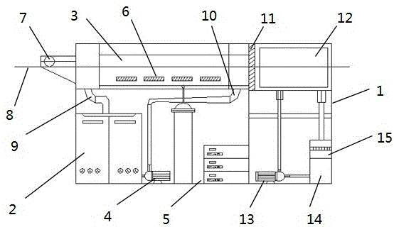
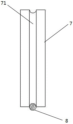
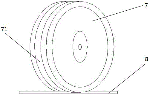
[0022] Embodiment 1: An ultrasonic cleaning machine for high-speed steel, the cleaning machine includes a frame; the frame is provided with an ultrasonic cleaning liquid storage tank and an ultrasonic generator; the upper end of the frame is provided with ultrasonic cleaning The ultrasonic cleaning tank is provided with an ultrasonic vibration plate; the ultrasonic cleaning liquid storage tank is connected to the ultrasonic cleaning tank through a circulating pump; the left side of the ultrasonic cleaning tank is provided with a high-speed steel feed port; the high-speed The steel feed port is provided with a guide roller for positioning the high-speed steel; the right side of the ultrasonic cleaning tank is provided with a clear liquid rinsing tank; the high-speed steel enters from the high-speed steel feed port The ultrasonic cleaning tank passes through the clear liquid rinsing tank; the clear liquid rinsing tank is provided with a rinsing liquid storage tank; the clear liquid rinsing tank and the rinsing liquid storage tank are connected through a rinsing pump.
[0023] There is a sponge wiping layer between the ultrasonic cleaning tank and the clear liquid rinsing tank. The sponge wiping layer is divided into a lower part and an upper part. The lower part is fixedly arranged, and the upper part is arranged above the high-speed steel by an elastic pressing block. The sponge wiping layer is used for wiping on the one hand The ultrasonic cleaning liquid on high-speed steel, on the other hand, is used to prevent the ultrasonic cleaning liquid in the ultrasonic cleaning tank from entering the clear liquid rinsing tank, and prevent the ultrasonic cleaning liquid from polluting the clear liquid in the clear liquid rinsing tank. The bottom left side of the ultrasonic cleaning tank is provided with a liquid outlet, and the bottom right side of the ultrasonic cleaning tank is provided with a liquid inlet; the liquid outlet is communicated with the ultrasonic cleaning liquid storage tank; the liquid inlet is communicated with the circulating pump.

Example Embodiment

[0024] Embodiment 2: An ultrasonic cleaning machine for high-speed steel, the cleaning machine includes a frame; the frame is provided with an ultrasonic cleaning liquid storage tank and an ultrasonic generator; the upper end of the frame is provided with ultrasonic cleaning The ultrasonic cleaning tank is provided with an ultrasonic vibration plate; the ultrasonic cleaning liquid storage tank is connected to the ultrasonic cleaning tank through a circulating pump; the left side of the ultrasonic cleaning tank is provided with a high-speed steel feed port; the high-speed The steel feed port is provided with a guide roller for positioning the high-speed steel; the right side of the ultrasonic cleaning tank is provided with a clear liquid rinsing tank; the high-speed steel enters from the high-speed steel feed port The ultrasonic cleaning tank passes through the clear liquid rinsing tank; the clear liquid rinsing tank is provided with a rinsing liquid storage tank; the clear liquid rinsing tank and the rinsing liquid storage tank are connected through a rinsing pump.
[0025] There is a sponge wiping layer between the ultrasonic cleaning tank and the clear liquid rinsing tank. The sponge wiping layer is divided into a lower part and an upper part. The lower part is fixedly arranged, and the upper part is arranged above the high-speed steel by an elastic pressing block. The sponge wiping layer is used for wiping on the one hand The ultrasonic cleaning liquid on high-speed steel, on the other hand, is used to prevent the ultrasonic cleaning liquid in the ultrasonic cleaning tank from entering the clear liquid rinsing tank, and prevent the ultrasonic cleaning liquid from polluting the clear liquid in the clear liquid rinsing tank. The bottom left of the ultrasonic cleaning tank is provided with a liquid outlet, and the bottom right of the ultrasonic cleaning tank is provided with a liquid inlet; the outlet is connected with the ultrasonic cleaning liquid storage tank; the liquid inlet is connected with the circulation pump, A filter is arranged in the ultrasonic cleaning liquid storage tank; the filter is in communication with the liquid outlet.

Example Embodiment

[0026] Embodiment 3: An ultrasonic cleaning machine for high-speed steel, the cleaning machine includes a frame; the frame is provided with an ultrasonic cleaning liquid storage tank and an ultrasonic generator; the upper end of the frame is provided with ultrasonic cleaning The ultrasonic cleaning tank is provided with an ultrasonic vibration plate; the ultrasonic cleaning liquid storage tank is connected to the ultrasonic cleaning tank through a circulating pump; the left side of the ultrasonic cleaning tank is provided with a high-speed steel feed port; the high-speed The steel feed port is provided with a guide roller for positioning the high-speed steel; the right side of the ultrasonic cleaning tank is provided with a clear liquid rinsing tank; the high-speed steel enters from the high-speed steel feed port The ultrasonic cleaning tank passes through the clear liquid rinsing tank; the clear liquid rinsing tank is provided with a rinsing liquid storage tank; the clear liquid rinsing tank and the rinsing liquid storage tank are connected through a rinsing pump.
[0027] There is a sponge wiping layer between the ultrasonic cleaning tank and the clear liquid rinsing tank. The sponge wiping layer is divided into a lower part and an upper part. The lower part is fixedly arranged, and the upper part is arranged above the high-speed steel by an elastic pressing block. The sponge wiping layer is used for wiping on the one hand The ultrasonic cleaning liquid on high-speed steel, on the other hand, is used to prevent the ultrasonic cleaning liquid in the ultrasonic cleaning tank from entering the clear liquid rinsing tank, and prevent the ultrasonic cleaning liquid from polluting the clear liquid in the clear liquid rinsing tank. The bottom of the clear liquid rinsing tank is provided with a clear liquid inlet and a clear liquid outlet; the clear liquid inlet is connected with the rinsing pump; the clear liquid outlet is connected with the rinse liquid storage tank.

PUM

no PUM

Description & Claims & Application Information

We can also present the details of the Description, Claims and Application information to help users get a comprehensive understanding of the technical details of the patent, such as background art, summary of invention, brief description of drawings, description of embodiments, and other original content. On the other hand, users can also determine the specific scope of protection of the technology through the list of claims; as well as understand the changes in the life cycle of the technology with the presentation of the patent timeline. Login to view more.
Why Eureka
Try Eureka