Automatic feeding structure for movable extrusion pads

A squeezing pad and automatic technology, applied in the field of extruders, can solve the problems of increased labor intensity, impossible manual operation, and contamination of particles by the squeezing pad, achieving a high degree of mechanical automation, reducing labor expeditiousness, and saving manpower Effect

Inactive Publication Date: 2017-06-09
田玥
View PDF0 Cites 0 Cited by
  • Summary
  • Abstract
  • Description
  • Claims
  • Application Information

AI Technical Summary

Problems solved by technology

[0002] At present, for high-precision micro-channel tube aluminum extrusion machines, the extrusion ratio is much higher than that of conventional aluminum extrusion machines, and the extruded aluminum alloy billet has low strength and high viscosity. If a fixed extrusion pad is used, it will seriously stick to aluminum. , the aluminum remaining on the inner wall of the extrusion cylinder is easily oxidized to produce impurity alloys, which reduces the weldability of the alloy and ultimately affects the quality of the extruded product. Therefore, most of the movable extrusion pads are used, but the existing active backlog pads are in the After the extrusion is finished, it is knocked off by scissors and dropped into the discharge trough, and then manually picked up and put into the trough, so that the extrusion pad is easy to stick to the polluted particles, which affects the quality of the extruded product, and the labor of the workers The strength is greatly enhanced, especially for machines with a capacity of more than 1,000 tons, manual operation is almost impossible

Method used


Image

  • Automatic feeding structure for movable extrusion pads

Examples


Embodiment 1

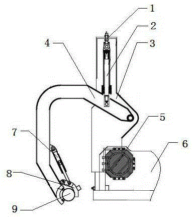
[0011] This embodiment provides an automatic trough-up structure for movable extrusion pads, which is characterized in that: the automatic trough-up structure for movable extrusion pads includes an adjustment bolt (1), a cylinder for gripping pad arms (2), a fixed seat (3), Gripping pad arm (4), fixed plate (5), extruder (6), pad clamping cylinder (7), pad gripping fixture (8), squeeze pad (9);

[0012] Among them: the gripping pad arm fixing seat (3) is fixedly installed on a corner of the extruder (5) through the fixed plate (4), and the gripping pad arm (4) is installed and connected through the gripping pad arm cylinder (2) and the movable pin shaft. The cushion arm cylinder (2) is fixedly installed on the fixed seat (3), and the upper end is also provided with an adjustment bolt (1), and the grasping cushion clamp (8) of the squeezing cushion (9) is arranged under the grasping cushion arm (4), and the grasping cushion One side of the clamp (8) is hingedly mounted with a p...


PUM


Abstract

The structure of the automatic trough-up of the movable extrusion pad is characterized in that: the automatic trough-up structure of the movable extrusion pad includes an adjustment bolt, an oil cylinder of the gripping pad arm, a fixed seat, a pad gripping arm, a fixed plate, an extruder, and a pad clamping cylinder , gripping pad fixture, extrusion pad; wherein: the gripping pad arm fixing seat is fixedly installed on one corner of the extrusion machine through the fixed plate, the gripping pad arm is installed and connected through the gripping pad arm oil cylinder and the movable pin shaft, and the gripping pad arm oil cylinder is fixedly installed on the On the fixed seat, the upper end is also provided with an adjusting bolt, and the gripping fixture of the extrusion pad is arranged under the gripping arm, and one side of the gripping fixture is hingedly installed with a cushion oil cylinder. The advantages of the present invention: the structure of the movable extrusion pad automatic grooving described in the present invention has a simple and compact structure, and realizes the rapid circulation of the extrusion pad, automatic reset, grooving and other operation processes, which saves manpower and reduces the labor burden of personnel. The high degree of mechanical automation meets the high requirements of modern mechanical production.

Description

technical field [0001] The invention relates to an extruding machine, and in particular provides an automatic groove-loading structure for a movable extruding pad. Background technique [0002] At present, for high-precision micro-channel tube aluminum extrusion machines, the extrusion ratio is much higher than that of conventional aluminum extrusion machines, and the extruded aluminum alloy billet has low strength and high viscosity. If a fixed extrusion pad is used, it will seriously stick to aluminum. , the aluminum remaining on the inner wall of the extrusion barrel is easily oxidized to produce impurity alloys, which reduces the weldability of the alloy and ultimately affects the quality of the extruded product. Therefore, most of the movable extrusion pads are used, but the existing active backlog pads are After the extrusion is finished, it is knocked off by scissors and dropped into the discharge trough, and then manually picked up and put into the trough, so that th...

Claims


Application Information

Patent Timeline
IPC IPC(8): B21C23/21
CPCB21C23/212
Inventor 田玥
Owner 田玥
Why Eureka
Try Eureka