
Automatic drawing device and automatic drawing method for optical fiber preform rod

An optical fiber preform and wire drawing technology, which is applied in manufacturing tools, glass manufacturing equipment, etc., can solve the problems of stable optical parameter performance that is difficult to control the fluctuation of optical fiber wire diameter, cannot realize automatic wire drawing, and affects the production of qualified optical fibers. Large promotion and application value, improved wire drawing efficiency, and easy installation

Active Publication Date: 2020-01-10
TONGDING INTERCONNECTION INFORMATION CO LTD
View PDF6 Cites 0 Cited by
  • Summary
  • Abstract
  • Description
  • Claims
  • Application Information

AI Technical Summary

Problems solved by technology

[0003] At present, domestic optical fiber drawing is basically semi-automatic drawing. In order to save costs, a small tail tube is used to connect the fiber preform for drawing. When drawing to the tail rod, due to the large difference between the diameter of the small tail tube and the diameter of the preform, human intervention is required. It is difficult to control the stability of fiber diameter fluctuations and the stability of various optical parameters, thus affecting the production of qualified fibers
For example, the prior art CN104211295A discloses an optical fiber drawing device and its drawing method. In the drawing device, the tail end of the optical fiber preform passes through the quartz glass tailpipe and the hanging rod platform, and human intervention is required to continuously intervene in the amount of rod feeding and the power of the drawing furnace. Therefore, the purpose of automatic wire drawing cannot be realized; at the same time, since the diameter of the quartz glass tail pipe of the wire drawing device is smaller than the diameter of the optical fiber preform, the change in the gap between the graphite heating element of the wire drawing furnace after entering the wire drawing furnace will inevitably affect the uniformity of the temperature field

Method used


Image

  • Automatic drawing device and automatic drawing method for optical fiber preform rod
  • Automatic drawing device and automatic drawing method for optical fiber preform rod
  • Automatic drawing device and automatic drawing method for optical fiber preform rod

Examples


Embodiment Construction

[0021] Exemplary embodiments of the present disclosure will be described in more detail below with reference to the accompanying drawings. Although exemplary embodiments of the present disclosure are shown in the drawings, it should be understood that the present disclosure may be embodied in various forms and should not be limited by the embodiments set forth herein. Rather, these embodiments are provided for more thorough understanding of the present disclosure and to fully convey the scope of the present disclosure to those skilled in the art.

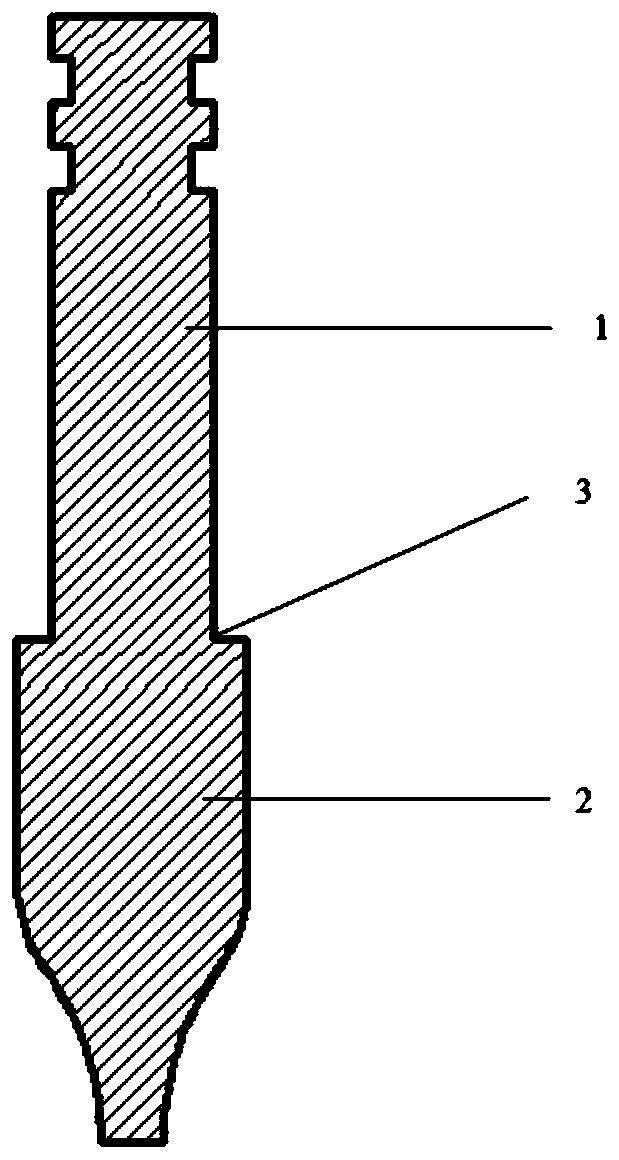
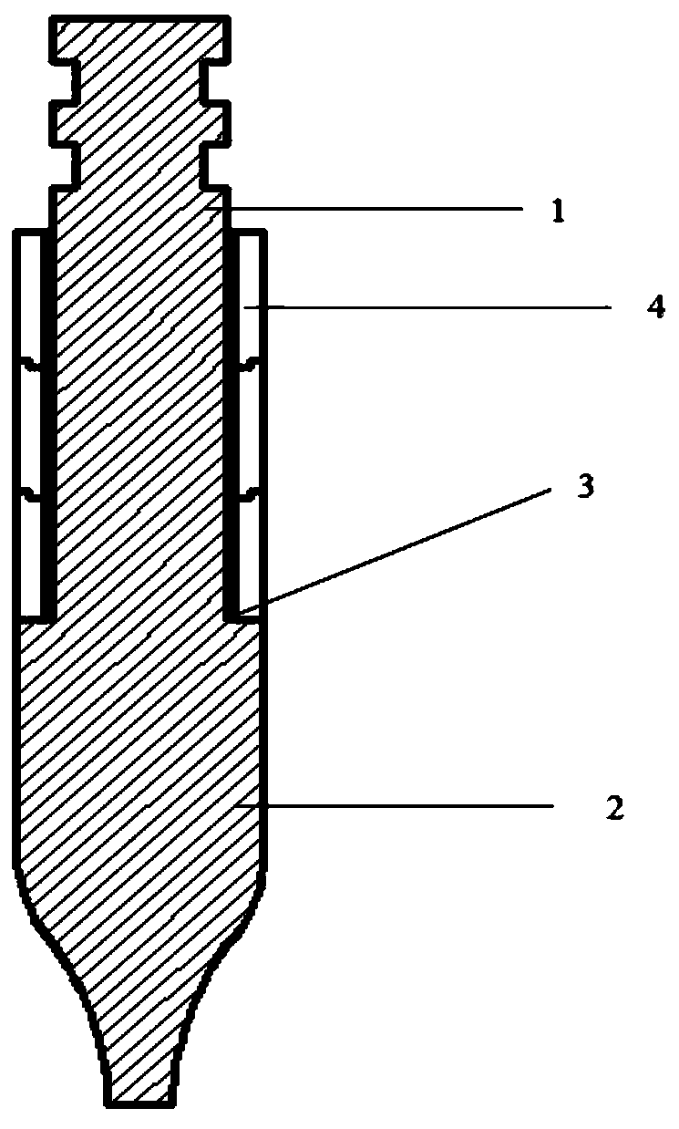
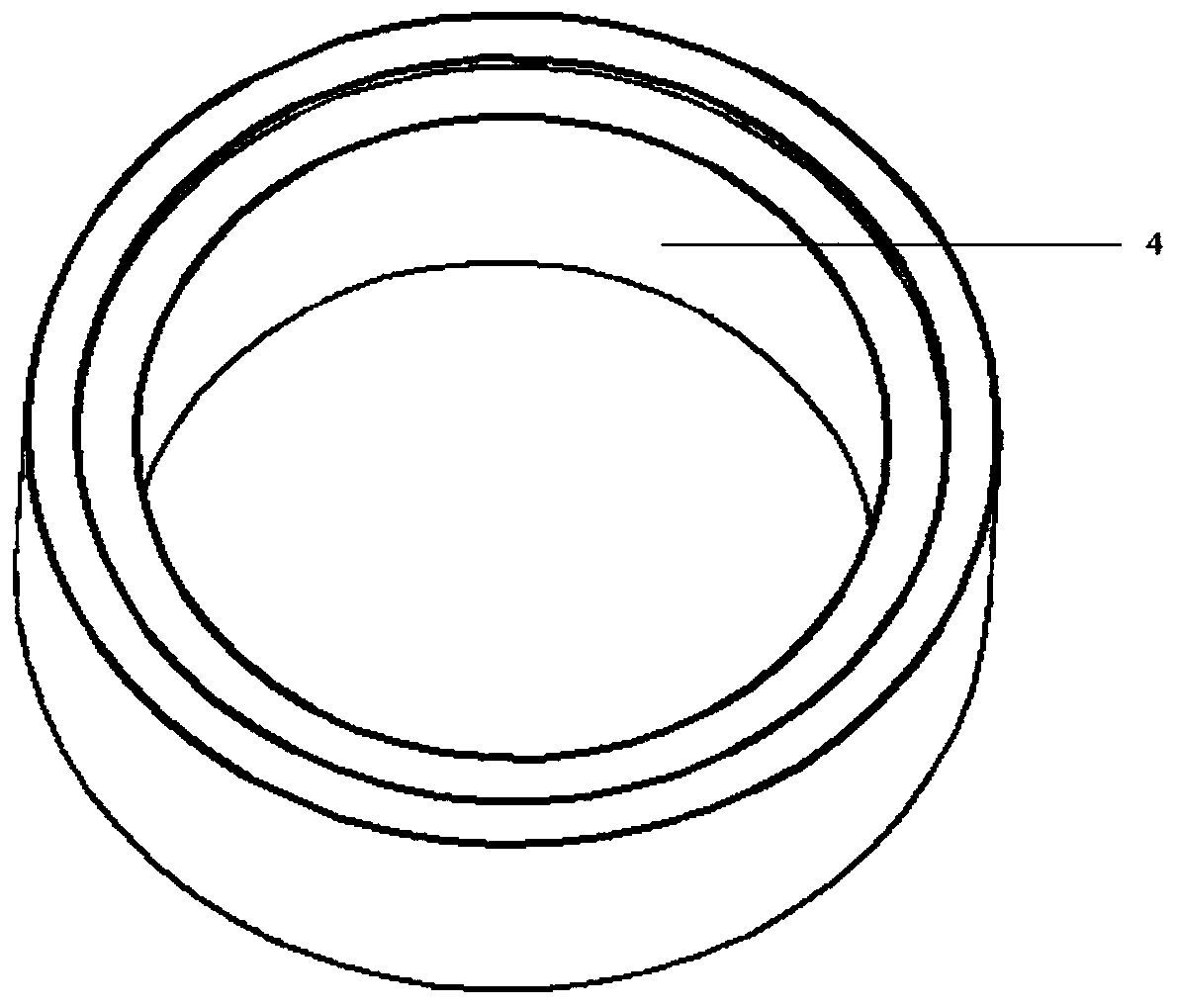
[0022] According to the embodiment of the present invention, an automatic drawing device for optical fiber preform is proposed, see Figure 1-Figure 4 , including a tail pipe 1, an optical fiber preform rod 2, a docking step 3, a quartz sleeve 4, a drawing furnace 5, a furnace mouth gas seal 6, and a furnace mouth metal gas plate 7; the diameter of the tail pipe 1 is smaller than the diameter of the optical fiber preform rod 2 , th...


PUM

PropertyMeasurementUnit
heightaaaaaaaaaa

Abstract

An automatic drawing apparatus for an optical fiber preform, comprising a tail tube, an optical fiber preform, an abutment step, quartz sleeves, a drawing furnace, a furnace opening air sealing port, and a furnace opening metal air plate. The diameter of the tail tube is less than that of the optical fiber preform; the optical fiber preform and the tail tube are welded together at high temperature to form the abutment step; the abutment step is perpendicular to the optical fiber preform; N quartz sleeves that are stacked from top to bottom are sleeved onto the outside of the tail tube and fitted onto the abutment step, wherein N ≥ 3; the optical fiber preform vertically passes through the furnace port metal air plate and is hung in the drawing furnace; the furnace opening air sealing port is provided in the furnace opening metal air plate.

Description

technical field [0001] The invention relates to an automatic wire drawing device and an automatic wire drawing method, in particular to an automatic wire drawing device and an automatic wire drawing method for an optical fiber preform. Background technique [0002] Optical fiber drawing is a process in which the preform is heated and melted by some kind of heating equipment, and then drawn into a small optical fiber with a diameter that meets the requirements, and the core / clad diameter ratio and refractive index distribution of the optical fiber are kept unchanged. It can be seen that the optical fiber preform and drawing process directly determine the production cost, quality and profit of optical fiber and cable enterprises, and improving the utilization efficiency of optical fiber preform raw materials has become the main direction of reducing the cost of optical fiber preform and optical fiber. [0003] At present, domestic optical fiber drawing is basically semi-automa...

Claims


Application Information

Patent Timeline
Patent Type & Authority Patents(China)
IPC IPC(8): C03B37/025
CPCC03B37/025
Inventor 沈小平田佳蒋锡华蒋小强朱坤唐成魏文涛
Owner TONGDING INTERCONNECTION INFORMATION CO LTD
Learn More