Self-resetting energy consumption support

An energy-dissipating support and self-resetting technology, which is applied to building components, earthquake resistance, and building types, can solve problems such as lateral buckling, difficult post-earthquake repairs, and large residual deformation of buckling-resistant supports.

Pending Publication Date: 2017-06-09
BEIJING UNIV OF TECH
View PDF6 Cites 7 Cited by
  • Summary
  • Abstract
  • Description
  • Claims
  • Application Information

AI Technical Summary

Problems solved by technology

[0003] The traditional common central support is prone to lateral buckling under the action of horizontal earthquake, especially under the action of reciprocating horizontal earthquake, when the stress of the structure enters the elastic-plastic range, the shear capacity and lateral stiffness of the floor will drop sharply, and it is easy to In the traditional eccentrically supported structural system, due to the large plastic deformation of the energy-dissipating beam section, it is extremely difficult to repair after the earthquake
The traditional buckling-resistant bracing member is an energy-dissipating shock-absorbing device for lateral force applied in multi-story structures. Under the action of moderate or large earthquakes, the buckling-resistant bracing member can fully yield the entire cross-section during tension and compression without The overall or local buckling failure of the supporting components changes the original energy dissipation mode through the plastic hinge at the beam end of the main structure to only the concentrated energy dissipation on the anti-buckling supporting parts, thereby better protecting the main structure; However, the residual deformation of buckling-resistant braces is relatively large, and the corresponding residual deformation of the overall structure is also relatively large, making post-earthquake repair difficult and costly
[0004] These traditional support members do not have self-resetting ability, so the post-earthquake repair is difficult, costly and takes a long time for normal use

Method used


Image

  • Self-resetting energy consumption support
  • Self-resetting energy consumption support
  • Self-resetting energy consumption support

Examples


Embodiment Construction

[0026] The present invention will be described in detail below in conjunction with the accompanying drawings. The embodiments described below with reference to the accompanying drawings are examples and are intended to explain the present invention, but should not be construed as limiting the present invention.

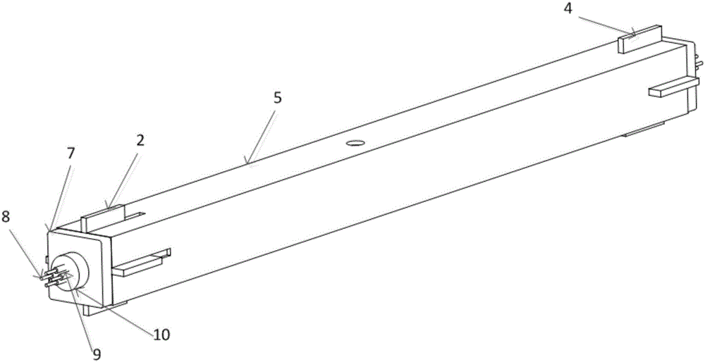
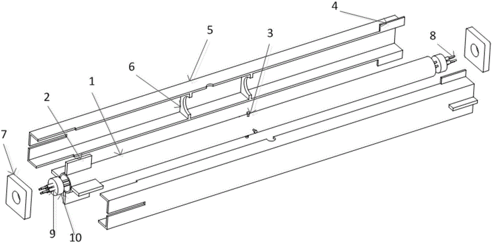
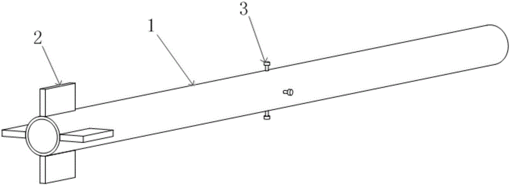
[0027] as attached figure 1 - attached Figure 6 As shown, the welding and assembling process of the present invention is all completed in the factory. In the factory, the wide ear plate (2), the shear rivet (3) and the inner restraint pipe (1) are welded and assembled, and the outer restraint pipe ear plate ( 4), the clapboard (6) and the outer restraint tube (5) are welded and assembled, and then the inner restraint tube (1) is arranged in the outer restraint tube (5), and then the cable (8) of the self-resetting system is inserted into the inner restraint through the opening of the fixed end plate (7), press the fixed end plate (7) tightly against the two ends of ...


PUM


Abstract

A self-resetting energy-dissipating support includes inner restraint pipes, outer restraint pipes, wide ear plates, shear rivets, lead sand, outer restraint pipe ear plates, partitions, fixed end plates, cables, clamps and anchor plates. In the factory, the wide lugs, shear rivets and inner restraint pipes are welded and assembled first, and the outer restraint pipe ear plates, partitions and outer restraint pipes are welded and assembled, and then the inner restraint pipes are arranged in the outer restraint pipes, and the outer restraint pipes are assembled. The restraint tube is re-welded and connected, and then the cable of the self-resetting system is inserted into the inner restraint tube, and then passed through the opening of the fixed end plate, and the fixed end plate is tightly pressed against the two ends of the outer restraint tube by applying prestress, tensioning The cable is anchored to the anchor plate with a clamp, and finally the lead sand is injected through the pouring hole to form a lead core, and the assembly is completed. The welding and assembling process of the present invention is all completed in the factory, and has the advantages of remarkable energy consumption effect due to the friction between the shear rivet and lead sand, strong self-resetting ability and high industrial production efficiency.

Description

technical field [0001] The invention relates to a self-resetting energy-consuming support, which belongs to the technical field of steel structure application. Background technique [0002] At present, the frame-support structure system is one of the most widely used structural systems in multi-story steel structures. As a relatively new type of building, the frame-bracing structure has excellent seismic performance, which is of great significance to our country's anti-seismic work. When an earthquake occurs, the steel support can bear most of the horizontal shear force and reduce the horizontal displacement of the overall structure. [0003] The traditional common central support is prone to lateral buckling under the action of horizontal earthquake, especially under the action of reciprocating horizontal earthquake, when the stress of the structure enters the elastic-plastic range, the shear capacity and lateral stiffness of the floor will drop sharply, and it is easy to ...

Claims


Application Information

Patent Timeline
Patent Type & Authority Applications(China)
IPC IPC(8): E04B1/98E04H9/02
CPCE04H9/021
Inventor 徐路白正仙刘学春崔小雄
Owner BEIJING UNIV OF TECH
Why Eureka
Try Eureka