
Novel engine oil dipstick

A technology of engine oil and oil dipstick, which is applied in the direction of engine components, machines/engines, mechanical equipment, etc. It can solve the problems that the oil and gas in the engine crankcase cannot be discharged in time, affect the safe operation of the engine, and block the crankcase ventilation pipe. Normal and safe operation, simple structure, simple and convenient operation

Active Publication Date: 2017-06-09
ANHUI JIANGHUAI NAVISTAR DIESEL ENGINE CO LTD
View PDF5 Cites 2 Cited by
  • Summary
  • Abstract
  • Description
  • Claims
  • Application Information

AI Technical Summary

Problems solved by technology

However, because the winter temperature in northern my country is often lower than -40°C, the hot oil and gas derived from the crankcase, at the intersection of the intake manifold, due to the accumulation of cold and hot air, it is easy to cause here to freeze and block the crankcase ventilation. As a result, the oil and gas in the engine crankcase cannot be discharged in time. Long-term operation will cause the pressure in the engine crankcase to be too high. Excessive pressure difference will cause the engine oil seal to leak or even fall off, which seriously affects the safe operation of the engine.

Method used


Image

  • Novel engine oil dipstick
  • Novel engine oil dipstick
  • Novel engine oil dipstick

Examples


Embodiment Construction

[0024] The embodiments of the present invention are described in detail below. This embodiment is implemented on the premise of the technical solution of the present invention, and detailed implementation methods and specific operating procedures are provided, but the protection scope of the present invention is not limited to the following implementation example.

[0025] In describing the present invention, it should be understood that the terms "center", "longitudinal", "transverse", "length", "width", "thickness", "upper", "lower", "front", " Orientation or position indicated by "back", "left", "right", "vertical", "horizontal", "top", "bottom", "inner", "outer", "clockwise", "counterclockwise", etc. The relationship is based on the orientation or positional relationship shown in the drawings, and is only for the convenience of describing the present invention and simplifying the description, rather than indicating or implying that the referred device or element must have ...


PUM


Abstract

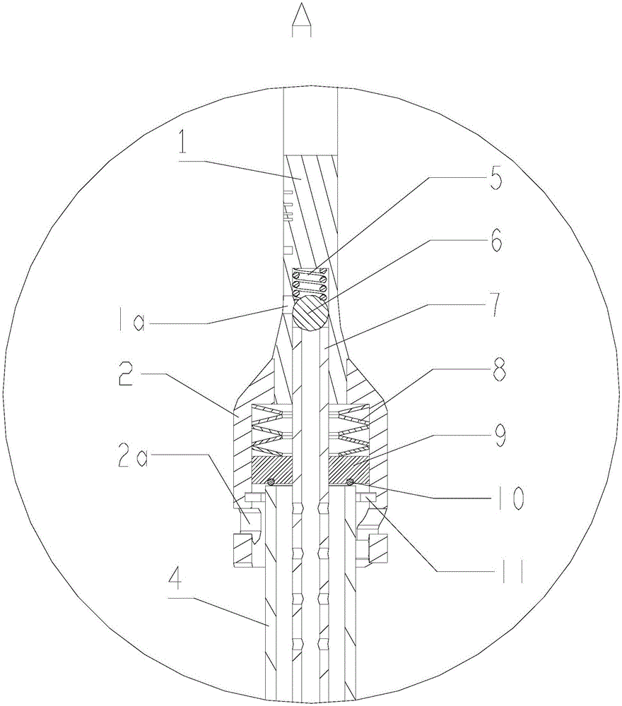
The invention discloses a novel engine oil dipstick. The dipstick comprises a handle, a lock catch, an oil dipstick core, and a guide tube, the end of the handle is sleeved with the lock catch, two locking grooves are respectively formed in the lower ends of the left and right sides of the lock catch, two short pins are respectively arranged at the left and right sides of the top end of the guide tube, and the two short pins are matched with the corresponding locking grooves to achieve self-lock of the guide tube and the lock catch; a vertical blind hole is formed in the middle of the bottom end of the handle, the oil dipstick core is fixed in the blind hole, the oil dipstick core penetrates through an cavity in the lock catch and the center of the guide tube from top to bottom in sequence, a ball valve and an air evacuation valve spring are arranged in the blind hole, the ball valve is pressed on the upper end face of the oil dipstick core by the air evacuation valve spring, and therefore a center hole of the oil dipstick core is sealed; a vent hole communicated with the top of the blind hole is formed in one side of the handle; a baffle is arranged in the cavity of the lock catch, and the baffle is pressed on the top face of the guide tube by a down press spring located on the top of the baffle. The novel engine oil dipstick has the advantages of providing a long-term and stable oil dipstick anti-loose scheme and a reliable crankcase pressure control scheme.

Description

technical field [0001] The invention relates to the technical field of engines, in particular to a novel engine oil dipstick. Background technique [0002] The engine oil dipstick is a common component used to measure the amount of oil inside the engine crankcase. [0003] In the prior art, the conventional oil dipstick is divided into a core and a sleeve. The core is inserted into the sleeve through the socket of the sleeve, and the elastic sealing ring on the core is radially compressed. The elastic sealing ring is usually a rubber product, and its elastic force generates friction on the surface of the ruler sleeve to tighten the ruler core and prevent the ruler core from unintentionally detaching from the ruler sleeve. However, due to the aging problem of rubber products, the elastic sealing ring will gradually lose its anti-loosening effect as the rubber ages. [0004] Secondly, with the increasingly stringent automobile emission regulations, closed forced crankcase ve...

Claims


Application Information

Patent Timeline
IPC IPC(8): F01M11/12F01M13/00
CPCF01M11/12F01M13/00F01M2013/0083
Inventor 葛锐朱文军周易赵杰吕庆伦金波朱贝贝
Owner ANHUI JIANGHUAI NAVISTAR DIESEL ENGINE CO LTD
Learn More