
Method for using a fastening device of an instrument working condition detection system

A detection system and fastening device technology, applied in the direction of supporting machines, mechanical equipment, etc., can solve the problems of camera looseness, time-consuming and physical strength, corrosion and other problems, achieve rapid disassembly and installation, improve service life, and increase detection range. Effect

Inactive Publication Date: 2017-06-09
重庆靖画工具有限公司
View PDF0 Cites 0 Cited by
  • Summary
  • Abstract
  • Description
  • Claims
  • Application Information

AI Technical Summary

Problems solved by technology

The most common installation method for monitoring equipment is usually to install a pole-type surveillance camera near the instrument. This installation method uses duckbill brackets and iron wires to fix the camera. However, during long-term use, the iron wire or duckbill bracket Corrosion will occur and the camera will become loose, which will affect the quality of information collection or monitoring
Moreover, during the installation or maintenance of many cameras, it takes a lot of time and physical effort to continuously move the cameras and duckbill brackets up and down, which greatly increases the workload of workers and further increases the total cost of precision instrument monitoring

Method used


Image

  • Method for using a fastening device of an instrument working condition detection system

Examples


Embodiment 1

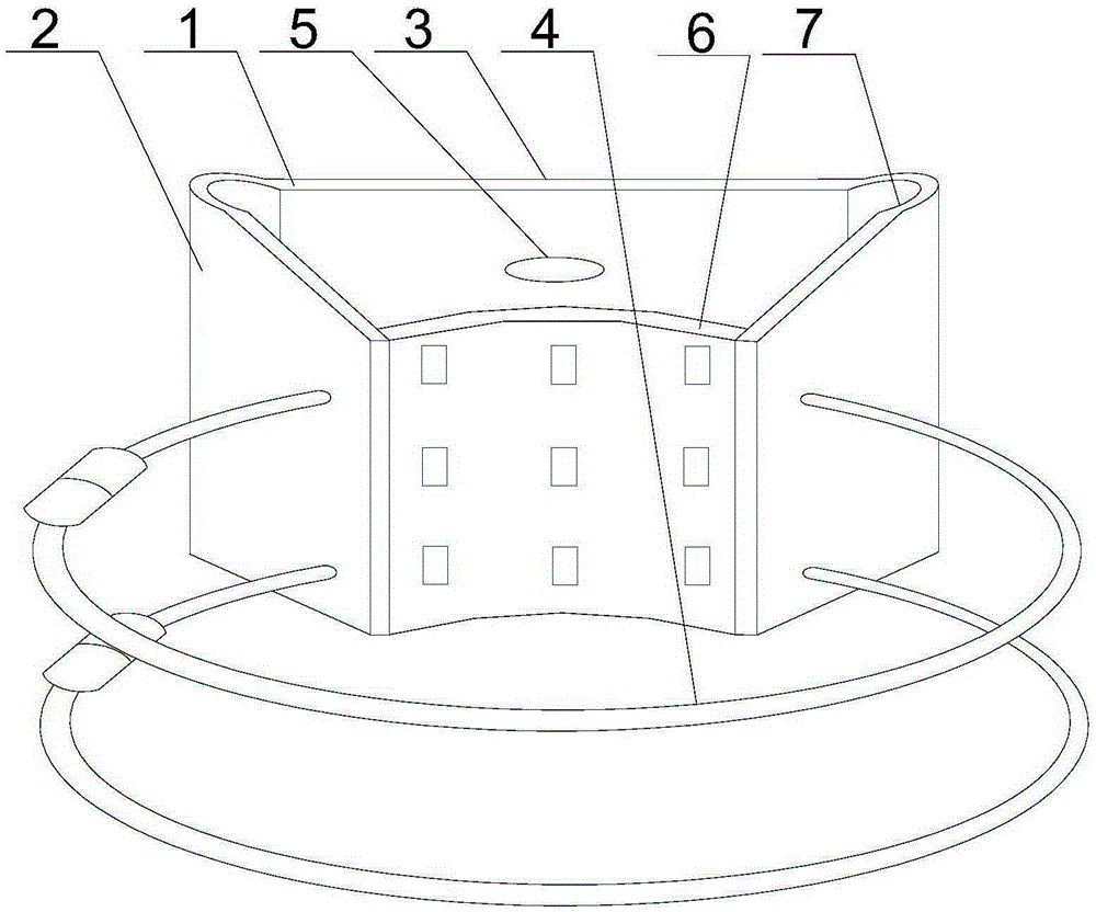
[0025] Such as figure 1 Shown, the present invention comprises the following steps:

[0026] A First place the ends of the two fixed plates on the rod-shaped support structure;

[0027] B Then fasten the dovetail-shaped mounting seat formed by the two fixed plates and the bottom plate on the outer peripheral wall of the dry support structure through the clamp;

[0028] C The adjustment plate can contact the outer circumferential wall of the support structure before the fixed plate contacts the outer circumferential wall of the support structure, so as to realize the flexible connection between the mounting seat and the support structure. When the monitoring equipment is shaken by external force, the elastic adjustment The plate can eliminate the generated stress through its own certain deformation and deformation recovery;

[0029] D When installing, the tension pad is directly attached to the outer peripheral wall of the support structure, and the multiple small holes opene...


PUM


Abstract

The invention discloses a method for using a fastening device of an instrument operating condition detection system, comprising the following steps: placing the ends of two fixing plates on a rod-shaped support structure; The mounting seat formed is fastened on the outer peripheral wall of the dry support structure; the adjusting plate can be in contact with the outer peripheral wall of the supporting structure before the fixed plate contacts the outer peripheral wall of the supporting structure, and when the monitoring equipment is shaken by an external force, the adjustment The plate can eliminate the acting stress; the tension pad is directly attached to the outer peripheral wall of the support structure during installation, and multiple small holes can increase the friction between the tension pad and the support structure; according to the installation height of the monitoring equipment, the The base of the monitoring equipment is fixed on the screw hole corresponding to its placement height by bolts. During use, the two clamps can ensure that there are multiple stress points between the mounting base and the supporting structure, that is, to ensure the stable placement of the monitoring equipment and avoid loosening and other phenomena.

Description

technical field [0001] The invention relates to a monitoring and fixing device, in particular to a method for using a fastening device of an instrument working condition detection system. Background technique [0002] In the process of processing precision parts, the precision instruments used are often expensive. Therefore, under the premise of ensuring the processing efficiency, how to ensure that the precision instruments are less likely to fail has become the focus of the manufacturing industry. At present, the method adopted is to conduct all-round state monitoring of precision instruments through monitoring equipment, to record its operating status data in real time, and to evaluate the feasibility of continuing to use the precision instruments through data analysis. The most common installation method for monitoring equipment is usually to install a pole-type surveillance camera near the instrument. This installation method uses duckbill brackets and iron wires to fix...

Claims


Application Information

Patent Timeline
Patent Type & Authority Applications(China)
IPC IPC(8): F16M13/02
Inventor 邹杰
Owner 重庆靖画工具有限公司
Learn More