Biological specimen tomography cutting and imaging device and the working method thereof
A technology of biological specimens and imaging equipment, applied in the field of biomedicine, can solve the problems of inability to obtain three-dimensional models, inconvenient for scientific research or teaching use, and ineffective methods for other biological tomography imaging.
- Summary
- Abstract
- Description
- Claims
- Application Information
AI Technical Summary
Problems solved by technology
Method used
Image

Examples
Embodiment 1
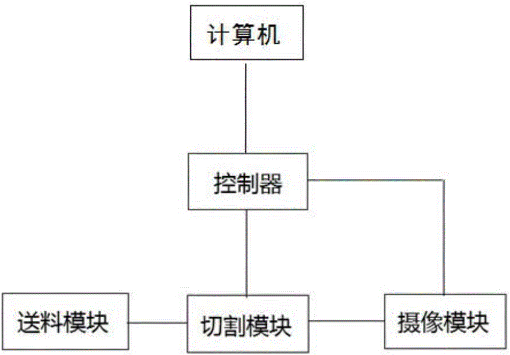
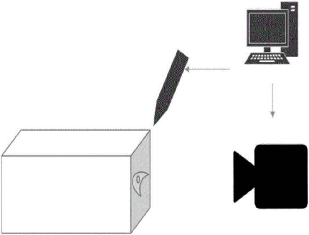
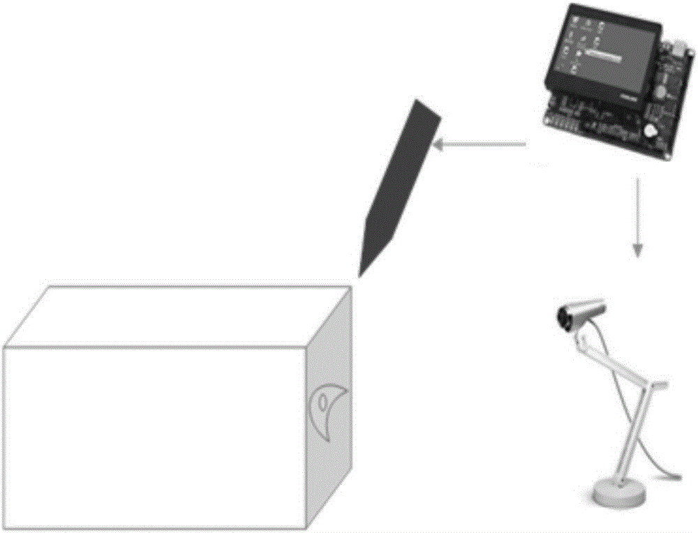
[0039] A biological specimen tomography imaging device, such as figure 1 As shown, it includes a feeding module, a cutting module, a camera module, a controller and a computer, the cutting module and the camera module are connected to the controller, the feeding module is connected to the cutting module, and the control module is connected to the computer;
[0040] The feeding module is used to transport the biological specimens to be cut, and controls the transport speed; in order to control the size of the cut specimens; the cutting module is used to cut the biological specimens, and is assisted by infrared cutting; the purpose is to obtain the thinnest sliced specimens. The camera module is used to photograph the section of the cut biological specimen; the controller is used to control the size of the biological specimen cut by the cutting module, and control the camera module to photograph the cut specimen, and save the photographed picture to the storage device; for exam...
Embodiment 2
[0045] The working method of the biological specimen tomography imaging device described in embodiment 1, such as Figure 4 As shown, the specific steps include:
[0046] (1) Specimen processing: fill and wrap the specimen with gypsum, and make it into a cuboid. It is convenient for subsequent uniform cutting, shooting of cut planes and computer data processing. The specimen designed as a rectangular parallelepiped is easy to clamp and cut. The images taken by the camera are generally rectangular images, and the cross-section is designed to be rectangular for easy imaging.
[0047] (2) The controller determines the cutting length of the biological specimen through the infrared module, and calculates the cutting time, including steps as follows:
[0048] A, by means of infrared ranging, according to the difference between the emission time and the reception time, the biological specimen cutting length s is obtained by the formula (I), and the formula (I) is as follows:
[00...
PUM
 Abstract
Description
Claims
Application Information
 - R&D
- Intellectual Property
- Life Sciences
- Materials
- Tech Scout
- Unparalleled Data Quality
- Higher Quality Content
- 60% Fewer Hallucinations
Browse by: Latest US Patents, China's latest patents, Technical Efficacy Thesaurus, Application Domain, Technology Topic, Popular Technical Reports.
© 2025 PatSnap. All rights reserved.Legal|Privacy policy|Modern Slavery Act Transparency Statement|Sitemap|About US| Contact US: help@patsnap.com