Induction cooker continuous low power control circuit and control method

A control circuit, low-power technology, applied in the field of induction cooker, can solve the problems of water rolling and stop, can not provide low-power stability, etc., to achieve the effect of continuous stable power

Inactive Publication Date: 2017-06-09
容小明
View PDF6 Cites 4 Cited by
  • Summary
  • Abstract
  • Description
  • Claims
  • Application Information

AI Technical Summary

Problems solved by technology

[0010] The core design shortcomings of low-cost electromagnetic heating devices are known to many users. The most obvious is that they cannot provide low power stability. The low power provided is only achieved by switching high power in time ratios. The situation where the water rolls and stops

Method used


Image

  • Induction cooker continuous low power control circuit and control method
  • Induction cooker continuous low power control circuit and control method
  • Induction cooker continuous low power control circuit and control method

Examples


Embodiment Construction

[0027] The preferred embodiments of the present invention are given below in conjunction with the accompanying drawings to describe the technical solution of the present invention in detail.

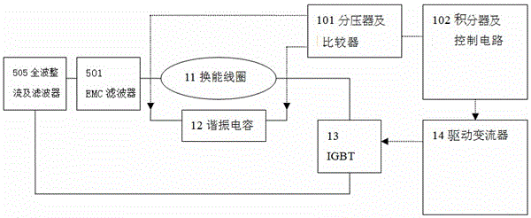
[0028] figure 1 It is a schematic diagram of the structure of the electromagnetic heating device of the present invention. The electromagnetic heating device adopts a structure in which the transduction coil is driven by high-frequency pulse width modulation energy and the iron low magnetic resistance cooking vessel is combined. The transduction coil 11 is composed of a resonant capacitor 12 One end of the LC resonant circuit is connected to the full-wave rectifier and filter 505 , and the other end is connected to form a loop through the IGBT 13 . The full-wave rectification and filter 505 provides a solution to make the circuit regard each positive and negative cycle of the mains power supply as two positive cycles, which are connected to one end of the LC resonant circuit, which is a ...


PUM


Abstract

The invention belongs to the induction cooker technical field, and specifically relates to an induction cooker continuous low power control circuit and a control method; the structure scheme can be implemented in a simple mode; the control circuit comprises a full wave rectification and filter; a transduction coil and a resonant capacitor are connected in parallel to form an LC resonance circuit; one end of the LC resonance circuit is connected with the positive end of the full wave rectification and filter, and the other end of the LC resonance circuit is connected with an IGBT collector electrode; an IGBT emitter electrode is connected with the negative end of the full wave rectification and filter, thus forming a current loop; the IGBT conduction time can be properly controlled, thus forming an electromagnetic heating device. In each T-on +T-lc period, a T-ext time period is added after the T-lc, so the period of the electromagnetic wave emitted by the induction cooker is T-on + T-lc + T-ext. T-on can be increased in a large power condition, and can be reduced when low power is needed; when T-on reaches the T-lc, the T-on is fixed, and the T-ext is imported, thus adjusting the T-ext so as to continuously adjusting the power rate. The control circuit and method can adjust the induction cooker power at will for cooking, thus allowing users to obtain the practical effect of using an open fire cook mode when the induction cooker is used.

Description

technical field [0001] The invention belongs to the technical field of electromagnetic ovens, and specifically refers to a continuous low-power control circuit and a control method for an electromagnetic oven. Background technique [0002] The transduction coil of the induction cooker is connected in parallel with the resonant capacitor to form an LC resonant circuit, and the LC resonant circuit is connected to the IGBT driving the converter. When the IGBT is turned on and off at the appropriate time, the energy passes through the transducing coil of the LC resonant circuit, and is directly transmitted to the iron cooking utensils by electromagnetic waves. [0003] Low-cost electromagnetic heating devices (induction cooker) generally use LC inductor-capacitor parallel resonant circuit as the management of the working sequence. [0004] The transducing coil L and the resonant capacitor C are connected in parallel to form an LC resonant circuit, and the LC resonant circuit is...

Claims


Application Information

Patent Timeline
Patent Type & Authority Applications(China)
IPC IPC(8): H05B6/06F24C7/08
Inventor 容小明
Owner 容小明
Why Eureka
Try Eureka