Modularized transverse moving device

A traverse device and modular technology, applied in the direction of metal rolling, metal rolling stands, manufacturing tools, etc., can solve the problems of complex traverse control means, poor maintenance, large volume, etc., to ensure smooth operation, weight Light, good synchronization effect

Active Publication Date: 2017-06-13
CHINA NAT HEAVY MACHINERY RES INSTCO
View PDF5 Cites 2 Cited by
  • Summary
  • Abstract
  • Description
  • Claims
  • Application Information

AI Technical Summary

Problems solved by technology

[0004] The purpose of the present invention is to overcome the problems of heavy weight, large volume, complex means of control of traversing and poor maintainability in the traversing mechanism of the existing intermediate roller, and to provide a modular traversing device

Method used


Image

  • Modularized transverse moving device
  • Modularized transverse moving device
  • Modularized transverse moving device

Examples


Embodiment 1

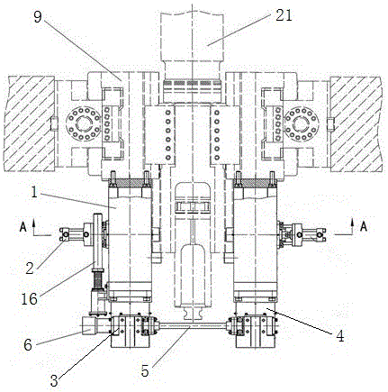
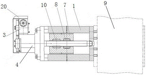
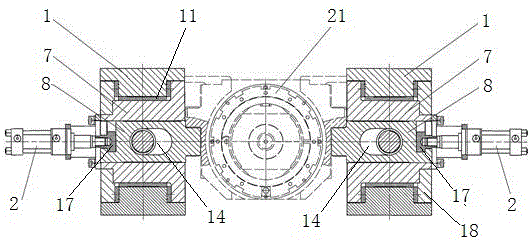
[0033] In order to overcome the problems of heavy weight, large volume, complicated means of traversing control and poor maintainability in the existing traversing mechanism of the intermediate roller, this embodiment provides a Figure 1 to Figure 7 The shown modular traverse device includes a frame 9 and two frame bodies 1 connected to the front end of the frame 9, the frame 9 is a symmetrical structure, and the two frame bodies 1 are symmetrically distributed on the center line of the frame 9 On both sides, slide blocks 7 are housed in the two frame bodies 1, and slideways 11 are provided on the upper and lower end surfaces of the slide block 1, and the slideways 11 on the upper and lower end surfaces of the slide block 7 are connected with the upper and lower end surfaces of the frame body 1 respectively. contact, and the slider 7 can slide back and forth in the frame body 1, the middle part of the slider 7 is provided with a through hole 12, and the through hole 12 is para...

Embodiment 2

[0039] On the basis of embodiment 1, this embodiment provides a kind of Figure 1 to Figure 7 In the modular traverse device shown, a position detector 16 is installed on the slider 7, and the position detector 16 is used to detect the position of the slider 7 to ensure the accuracy of the roller traverse position and realize automatic traverse control .

[0040] Further, in order to improve the maintainability of the position detector 16, the position detector 16 is installed externally.

Embodiment 3

[0042] On the basis of embodiment 2, this embodiment provides a kind of Figure 1 to Figure 7 Modular traversing units shown, such as Figure 7 As shown, one end of the locking pin 8 is provided with a T-shaped slot, and the bottom of the T-shaped slot is arc-shaped, and the other end is stepped. Blocked during operation to ensure unimpeded operation, the side surface of the locking pin 8 is also processed with a lubricating oil groove, which is convenient for adding lubricating oil to ensure the operation of the locking pin.

[0043] Further, such as Figure 6 As shown, one end of the locking pin 3 is connected to the piston rod of the locking cylinder 2 through a plug 17 . One end of the top 17 is provided with a step, and the step is stuck in the T-shaped groove of the locking pin 8 and matches with the T-shaped groove of the locking pin 8. The other end of the top 17 is provided with a threaded blind hole, which is connected with the locking cylinder 2 Piston rod connecti...


PUM


Abstract

The invention relates to a modularized transverse moving device. The modularized transverse moving device comprises two frame bodies symmetrically connected to the front end of a machine frame; sliding blocks are arranged in the two frame bodies; slideways are arranged on the upper end surfaces and the lower end surfaces of the sliding blocks, and the slideways on the upper end surfaces and the lower end surfaces of the slide blocks make contact with the upper end surfaces and the lower end surfaces of the frame bodies respectively; through holes I are formed in the middle of the sliding blocks and are parallel to the slideways; screw boxes are arranged on the two frame bodies respectively; screws on the screw boxes penetrate through the through holes I; nuts are arranged on the outer sides of the screws in a sleeving mode and are fixed in the through holes I; sliding grooves are further formed in the sliding blocks and are perpendicular to the slideways; the through holes I penetrate through the sliding grooves; locking pins are arranged in the sliding grooves; locking oil cylinders are connected outside the sliding grooves; one ends of the locking pins are connected to piston rods of the locking oil cylinders; through holes II are formed in the locking pins, and the through holes I communicate with the through holes II all the time; positioning blocks are further arranged on the sides, opposite to the locking oil cylinders, of the sliding blocks; two speed reducers are arranged at the outer ends of the two screws respectively and are connected through a coupler; and a hydraulic motor is connected to one of the speed reducers.

Description

technical field [0001] The invention relates to the technical field of steel rolling equipment, in particular to a modular traverse device. Background technique [0002] In the strip rolling production process, in order to control the shape of the strip and reduce the edge thinning of the strip, it is necessary to control the contact length of the roll surface between the rolls. At the same time, in order to maintain the stability of the rolling process, the working roll and backup roll The position is generally fixed and locked, so an intermediate roll is set between the work roll and the backup roll. By changing the length of the contact roll surface between the intermediate roll and the work roll and the backup roll, the thinning of the edge of the strip can be reduced and the improvement can be achieved. Plate purpose. For different board widths, the positions of the intermediate rollers are also different, so a special mechanism is required to realize the lateral movem...

Claims


Application Information

Patent Timeline
Patent Type & Authority Applications(China)
IPC IPC(8): B21B37/40B21B31/18
CPCB21B31/18B21B37/40
Inventor 苏旭涛尤磊徐利璞刘云飞苏明
Owner CHINA NAT HEAVY MACHINERY RES INSTCO
Why Eureka
Try Eureka