Check patentability & draft patents in minutes with Patsnap Eureka AI!

Digital controlled swinging mechanism for polishing aspheric optical element

An optical element and aspheric technology, which is used in optical surface grinders, grinding/polishing equipment, grinding machine parts, etc. Processing efficiency and processing accuracy, reduction of intermediate frequency error, and the effect of light driving part

Active Publication Date: 2017-06-13
SHANGHAI INST OF OPTICS & FINE MECHANICS CHINESE ACAD OF SCI
View PDF5 Cites 12 Cited by
  • Summary
  • Abstract
  • Description
  • Claims
  • Application Information

AI Technical Summary

Problems solved by technology

The X-axis of the machine is a swing axis, and the Y-axis is a telescopic axis, both of which are controlled by servo motors. If the polishing head is to run according to the set trajectory, the servo motor may not do uniform circular motion, but complex variable speed motion. , it is impossible for the motor to do complex variable speed movement to have a high speed, which means that the moving speed of the polishing head is limited. At the same time, due to the use of an actively driven polishing head, the moving speed of this type of polishing head is further limited due to its large mass. , then the polishing head of the machine tool rotates, and the whole moves at a lower speed. Accordingly, this invention is no different from the traditional CNC polishing method (CCOS). The position of the shaft on the wobble plate reduces the eccentricity, so that the X-axis driving motor can rotate at a constant speed throughout the entire circle. Although the X-axis moving speed can be improved to a certain extent, it is still limited by the high-quality polishing head and cannot be very high. On the other hand, the polishing trajectory is single at this time, which cannot meet the needs of component processing
[0003] In summary, the movement of this invention is not flexible enough, it is no different from the traditional CNC polishing method (CCOS), it cannot replace the traditional tape repair method, and it cannot achieve the positive effect mentioned
[0004] Using a small tool to repair the belt does not require much force. The traditional CNC polishing method (CCOS) is processed by a heavy machine tool, which has poor flexibility and poor processing quality. In many cases, manual repair is still required, but manual repair of aspheric optical components is laborious. The shortcomings of high strength and difficult to control the surface shape accurately, so there is an urgent need for a polishing equipment that can replace manual repair in aspheric optical processing

Method used


Image

  • Digital controlled swinging mechanism for polishing aspheric optical element
  • Digital controlled swinging mechanism for polishing aspheric optical element
  • Digital controlled swinging mechanism for polishing aspheric optical element

Examples


Embodiment Construction

[0028] The present invention will be further described in conjunction with embodiment now.

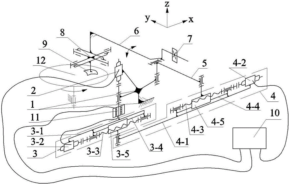
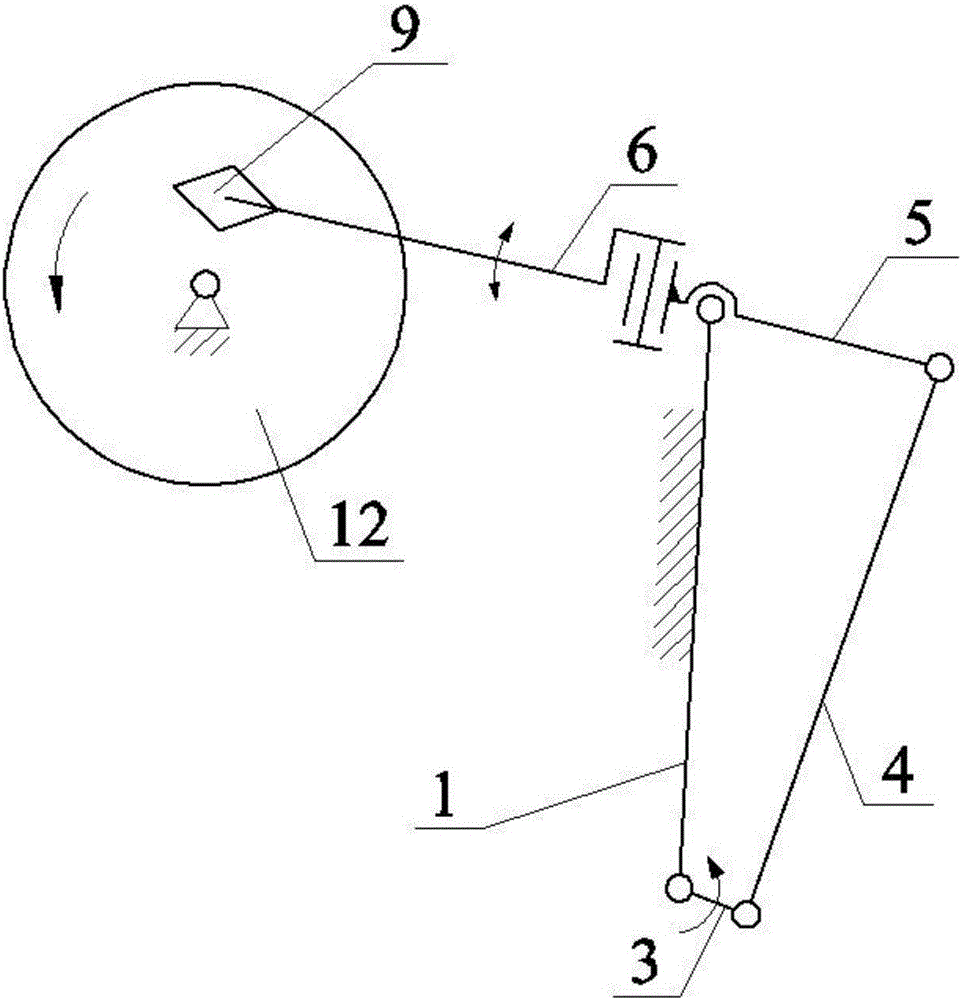
[0029] see figure 1 , figure 1 It is a schematic diagram of the structure of the CNC pendulum used for polishing aspheric optical elements in the present invention, including a frame 1, a spindle motor 2, an electronically controlled crank 3, an electronically controlled connecting rod 4, a rocker 5, a swing arm 6, a counterweight 7, and a cross Universal joint 8, polishing disc 9, controller 10 and electric slip ring 11, described electric control crank 3 comprises crank frame 3-1, crank motor 3-2, crank screw rod 3-3, crank guide rail 3-4 And crank slide table 3-5, described electric control connecting rod 4 comprises connecting rod frame 4-1, connecting rod motor 4-2, connecting rod screw rod 4-3, connecting rod guide rail 4-4 and connecting rod slide table 4-5;

[0030] The crank frame 3-1, crank motor 3-2, crank screw 3-3, crank guide rail 3-4 and crank slide table 3-5 of the e...


PUM


Abstract

The invention relates to a digital controlled swinging mechanism for polishing an aspheric optical element. The digital controlled swinging mechanism mainly comprises a machine frame, a main shaft motor, an electrical-controlled crank, an electrical-controlled connecting rod, a rocker, a swinging arm, a balancing weight, an universal joint cross, a polishing disk, a controller and an electric slip ring, wherein the length of the electrical-controlled crank and the length of the electrical-controlled connecting rod can be controlled by the controller, so that the swinging amplitude and the swinging position of the aspheric strip repairing and polishing disk are controlled. According to the digital controlled swinging mechanism disclosed by the invention, the process of manually repairing strips during polishing the aspheric optical element can be replaced, the processing efficiency is improved, the shortcomings that manual strip repairing is inaccurate in track control, and uneven in polishing pressure distribution are overcome; and the processing accuracy is improved.

Description

technical field [0001] The invention relates to optical processing, in particular to a numerically controlled pendulum mechanism for polishing aspheric optical elements. Background technique [0002] In the patent "A CNC Polishing Manipulator for Large-Aperture Optical Components" (Patent Publication No. CN 101386146 B), a CNC oscillating polishing machine is introduced. The X-axis of the machine is a swing axis, and the Y-axis is a telescopic axis, both of which are controlled by servo motors. If the polishing head is to run according to the set trajectory, the servo motor may not do uniform circular motion, but complex variable speed motion. , it is impossible for the motor to do complex variable speed movement to have a high speed, which means that the moving speed of the polishing head is limited. At the same time, due to the use of an actively driven polishing head, the moving speed of this type of polishing head is further limited due to its large mass. , then the pol...

Claims


Application Information

Patent Timeline
IPC IPC(8): B24B13/00B24B47/00
CPCB24B13/00B24B47/00
Inventor 焦翔谭小红朱健强
Owner SHANGHAI INST OF OPTICS & FINE MECHANICS CHINESE ACAD OF SCI
Features
  • R&D
  • Intellectual Property
  • Life Sciences
  • Materials
  • Tech Scout
  • Unparalleled Data Quality
  • Higher Quality Content
  • 60% Fewer Hallucinations
Learn More