
Dumping device applicable to non-self-dumping flat truck

A technology of unloading device and automobile, which is applied in the direction of freight vehicles, loading and unloading vehicle arrangements, motor vehicles, etc. It can solve the problems of insufficient length of excavator arms, time-consuming and laborious unloading of goods, etc., so as to reduce loss, The effect of increasing the unloading speed and improving the unloading efficiency

Active Publication Date: 2017-06-13
合山锌业科技有限公司
View PDF13 Cites 0 Cited by
  • Summary
  • Abstract
  • Description
  • Claims
  • Application Information

AI Technical Summary

Problems solved by technology

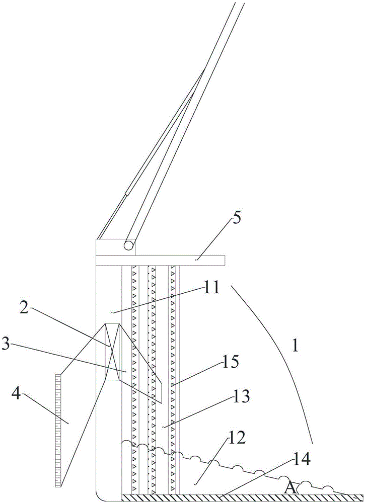
[0002] Existing cargo flatbed trucks are self-unloading, which can automatically tilt the container for unloading, but at present, more non-dumping flatbed trucks still rely on manpower for unloading, and some rely on excavators for unloading , but the arm of the excavator is not long enough to reach the top of the flatbed truck container, and auxiliary manpower is still needed to unload the goods, especially for the transportation of coal and other bulk and granular blend materials, manpower unloading is time-consuming and laborious, however The problem that the excavator arm cannot be unloaded cleanly at one time only by lengthening the arm of the excavator

Method used


Image

  • Dumping device applicable to non-self-dumping flat truck
  • Dumping device applicable to non-self-dumping flat truck

Examples


Embodiment Construction

[0032] The present invention will be further described in detail below in conjunction with the accompanying drawings, so that those skilled in the art can implement it with reference to the description.

[0033] It should be noted that the experimental methods described in the following embodiments, unless otherwise specified, are conventional methods, and the reagents and materials, if not otherwise specified, can be obtained from commercial sources; in the description of the present invention, The terms "landscape", "portrait", "top", "bottom", "front", "rear", "left", "right", "vertical", "horizontal", "top", "bottom", The orientation or positional relationship indicated by "inner", "outer", etc. is based on the orientation or positional relationship shown in the drawings, which is only for the convenience of describing the present invention and simplifying the description, and does not indicate or imply that the referred device or element must have Certain orientations, co...


PUM


Abstract

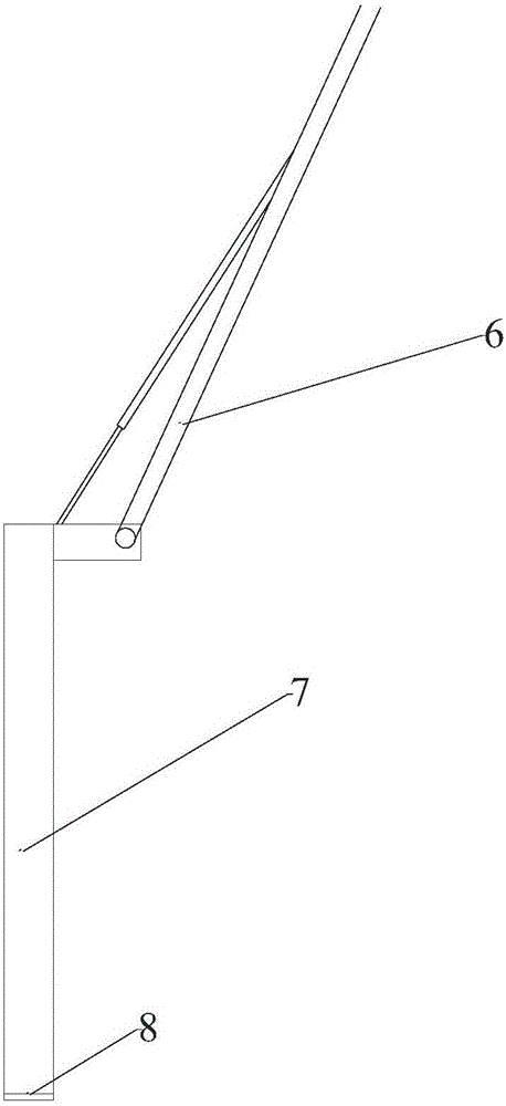
The invention discloses a dumping device applicable to a non-self-dumping flat truck. The dumping device comprises a truck body, a cab and a first movable arm, wherein the first movable arm is connected with a first dumping rake, the first dumping rake comprises a dumping bucket, the dumping bucket comprises a material blocking box plate, a material scraping plate, two lateral plates, a first brush, a second brush, an exhaust fan, a material-guide flat mouth, a material-sucking flat mouth and a dustproof plate, the slope of the material scraping plate is upwardly arranged to allow the material scraping plate and the material blocking box plate to form an L shape, the two lateral plates are respectively arranged on the left and right sides of the material scraping plate, the first brush comprises first brush bodies respectively arranged on the left and right sides of the material scraping plate, the second brush comprises brush layers respectively arranged on the outer sides of the two lateral plates, the exhaust fan is arranged in the cylindrical cavity of the material blocking box plate and electrically connected with a fan switch, the material-guide flat mouth is arranged on one side, with the material scraping plate, of the material blocking box plate, one end of the material-guide flat mouth is communicated with a material guide port, the material-sucking flat mouth is arranged on the other side of the material blocking box plate, one end of the material-sucking flat mouth is communicated with a material sucking port, and the dustproof plate is arranged at the top of the material blocking box plate. The dumping device is simple in structure, easy to operate and clean in dumping.

Description

technical field [0001] The invention relates to the technical field of unloading equipment. More specifically, the present invention relates to a discharge device suitable for non-dump flatbed vehicles. Background technique [0002] Existing cargo flatbed trucks are self-unloading, which can automatically tilt the container for unloading, but at present, more non-dumping flatbed trucks still rely on manpower for unloading, and some rely on excavators for unloading , but the arm of the excavator is not long enough to reach the top of the flatbed truck container, and auxiliary manpower is still needed to unload the goods, especially for the transportation of coal and other bulk and granular blend materials, manpower unloading is time-consuming and laborious, however Only by lengthening the arm of the excavator, it is impossible to unload the cargo cleanly at one time. Contents of the invention [0003] It is an object of the present invention to solve at least the above-me...

Claims


Application Information

Patent Timeline
Patent Type & Authority Applications(China)
IPC IPC(8): B60P1/48
CPCB60P1/483
Inventor 骆湘平
Owner 合山锌业科技有限公司
Learn More